sT[J
--]
=E,-
FEVOX
llerkzeug:
Es wjrd folgendes l,lerkzeug
benöti9t:
1
Kreuzschl i tzschraubendreher Nr.
2
1 Inbusschlüssel
(lnsec)
3 mm
I'JARNUNG:
Das Gerät und der lR-Receiver
Print
entha
I ten elektrostatisch empfindli-
che
Bauteile. Der tinbaLr sol
lte nur
an entsprechend
geschü
tzten
Arbejts-
pl
ätzen durchgefrjhrt \lerden.
Vorbere
i tu ng :
Am
Gerät
Netzstecker ausziehen.
DLrrch
Lösen
der beiden Schrauben an
der
Rückseite
das
obere
Deckblech nach
hinten liegziehen.
Das Gerät auf die
rechte Seitenwand stellen.
llm das
untere Deckblech zu demontieren,
zu-
erst
die vordere Fussleiste entfer-
nen. Danach die vier Schrauben an
der Geräteunterseite und eine Schrau-
be
an
der Rückseite
(14itte)
lösen.
:,
_
:-'
_a
a:'a.:r :
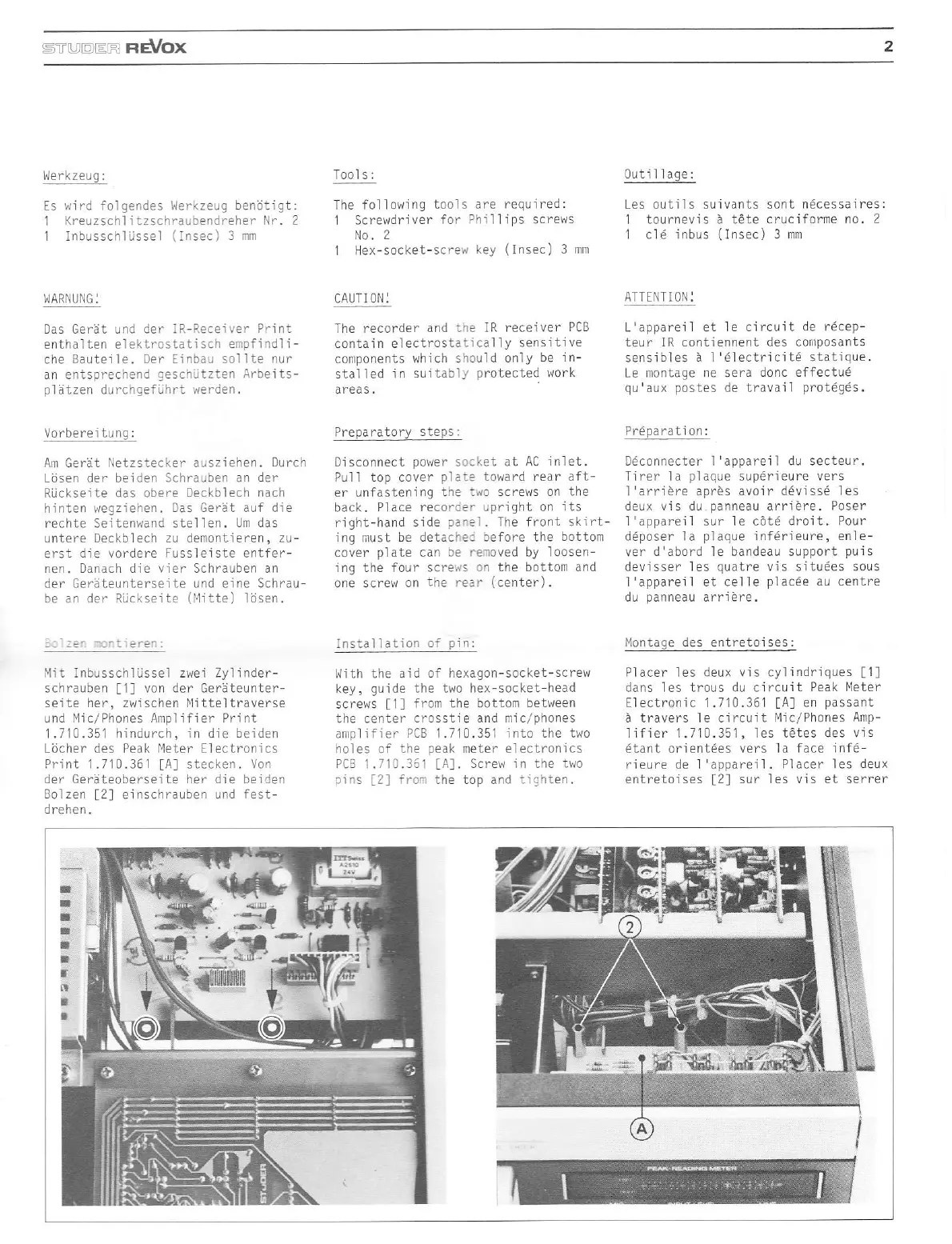
!-r. lr b"ss( 1l
;ssel
zwe- Z!'
ilde(-
schrauben
[1]
von der Geräteunter-
seite her, zwjschen l'litteltraverse
und l,lic/Phones Amplifier Print
1.710.351 hindurch,
jn
die
beiden
Löcher des Peak lleter Electronics
Pri nt I .71 0.361
[A]
stecken . Von
der Geräteoberseite her die beiden
Bolzen
[2]
einschra!ben
und fest-
drehen
-
Tool s:
The fol I
olii
ng
tool s
are
J
Screwdri
ver for
?hill
No.
2
1 Hex-socket-scre!l
key
requ
j
red
:
i
ps
screws
(Insec)
3 mm
CAUT] ON:
The recorder
and ire
IR receiver
PCB
contain
el ectrostati
cal ly sens
j
ti ve
conrponents
which should
only
be in-
stalled in
suitably
protected
work
areas.
Prepa ratory
steps:
Disconnect
povier
s:cket al
AC inlet.
Pull top cover
plaie
toward redr aft_
er unfastenjng
the:i{o screws
on the
back.
Place recorc.'!pright
on its
right-hand
side
p.'el.
The front skirt-
ing nust be
detacie. before the
bottom
cover
plate can be renoved by loosen-
in9 the four scre!/s
on the bottom and
one
screw on
the rear
(center).
Inslallation
of
pin:
l,lith the aid
of hexagon-socket-screw
key,
guide the tllo hex-socket-head
screr,/s
ll
from the
bottom between
the certer
crosstie and mic/phones
ariplifier
PCB
1.710.351
into the t\,ro
holes of the
peak
meter electronics
PCB
1.710,351
[A].
Screw in the two
o
r'
-2
--o:
-.e
_op
ard L
l\rö1.
0utillage:
Les outils s!ivants sont
ndcessaires:
I tourneviS ä tete
crucifonne no.2
I cl6 inbus
(lnsec)
3
mm
ATTENTI
ON:
L'oppo'qi el
F
c_rruiL
de recef-
teur lR contjennent
des coriposants
sensibles
ä l'6lectricitd statique.
Le montage ne sera
donc effectu6
qu'aL posre, de
I
rdva
:l
orot6ges.
Prdpa rati on:
De'oar ec ter I'appare'l du SeLLp-..
Tirer la
plaque
sup6rieure vers
l'arriöre aprös avoir ddvisse les
deux
vis
du
panneau
arrjere. Poser
l'appareil sur
le cötd droit. Pour
ddposer la
plaque
infdrieure, enle-
ve- d'öoord lF barded" sJpport
puis
devisser
les
quatre
vis situ6es sous
I'appareil et celle
plac6e
au centre
du
panneau
arriöre.
l,lontage des
entretoises:
Placer les deux vis cyl
indriques
[1]
dans les trous du circuit
Peak I'leter
Electron'ic
1.710.361
tAl
en
passant
ä travers le circuit
f4ic/Phones Amp-
Lf ier l./10.'5
,
les Lötes
des v1<
6lant orientdes vers
la face inf6-
rieure
de
I'appareil.
Placer les
deux
entretoises
f2l
sur les vis et serrer
 Loading...