INDEX
Sr.
No.
Para.
Description
1
Set Point
3
P2
4
P3
5
HS
6
LS
7
P4
8
P5
9
P6
Compressor relay set point.
High temperature limit.
Low temperature limit.
Maximum Set Point limit.
Minimum Set Point limit.
Differential for compressor relay ON condition.
Probe calibration for room.
Time delay (compressor relay restart after cutoff).
2
Set other parameter.
Compressor relay ON time during probe fault.
10
Ot
Minimum ON time for compressor relay.
Compressor relay status in probe fail.
11
E1
12
Cn
13
Cy
14
15
16
17
Compressor relay OFF time during probe fault.
19
20
21
E2
E3
E4
E5
Set type of defrost
Set drip time for defrost water to drain out.
Set post drip time.
Defrost duration during coil probe fail.
P7
P8
Defrost duration & manual defrost.
Defrost frequency.
P9
Power ON defrost delay.
L2
L3
L4
L5
L6
To set time delay between Evap. fan relay
restart time
Evap. Fan operation when compressor is OFF.
Evap. Fan differential (Hysteresis).
Probe 2 offset calibration (Evap. fan coil probe)
Evap. fan status during defrost.
L1
Evap. fan stop temp Coil.
L7
Defrost stop temperature (Evap Coil probe).
do1
do2
do3
CF0
CF1
Door Open fault Sensing delay.
Compressor / Fan Status on Door Open Fault.
Delay time for Temperature updating at door
open digital input fault.
Activate or deactivate Compressor Fault digital
input.
Compressor Fault digital input Sensing delay.
do0
Activate or deactivate door open digital input.
22
23
24
25
26
27
28
29
30
31
32
33
Change Password
Keypad Lock
Restore factory defaults
End Programming
Time delay at Power ON for alarm indication.
Delay the display of temperature.
dd
Ad
PA
LP
FS
EP
LED Indications
Password Function
Temperature Logging
User Selectable Default Values
CF2
Compressor / Fan Status on Compressor Fault
digital input.
CF4
No of retrials of compressor when Manual
reset is selected.
ddF
Display during defrost.
nd
Default (Normal) Display.
To set controller Resolution
rS
34
37
38
39
40
41
42
43
44
45
46
47
CF3
Set reset mode for Compressor output, on
Compressor Fault digital input.
35
Operating Messages
18
E6
Computation method for defrost.
36
48
CAUTION
WIRING: The probe and its corresponding wires should never be
installed in a conduit next to control or power supply lines. The electrical
wiring should be done as shown in the diagram. The power supply circuit
should be connected to a protection switch. The terminals admit wires of
upto 2.5sq mm.
Maintenance: Cleaning: Clean the surface of the controller with a soft
moist cloth. Do not use abrasive detergents, petrol, alcohol or solvents.
Notice: The information in this document is subject to change in order to
improve reliability , design or function without prior notice and does not
represent a commitment on the part of the company. In no event will the
company be liable for direct, indirect, special, incidental or consequential
damage arising out of the use or inability to use the product or
documentation, even if advised of the possibility of such damages. No
part of this manual may be reproduced or transmitted in any form or by
any means without the prior written permission of the company.
WARNING: Improper wiring may cause irreparable damage and
personal injury. Kindly ensure that wiring is done by qualified personnel
only.
To fix the unit, slide the fastener 1 through the guides 2 as per the
position shown in the figure. Move the fastener in the direction of the
arrow, pressing tab 3 it permits to move the fastener in the opposite
direction of the arrow.
Installation : Fixing and dimensions of panel models:
Controller :Controller should be installed in a place protected by
vibration, water and corrosive gasses and where ambient temperature
does not exceed the values specified in the technical data.
Probe :To give a correct reading, the probe must be installed in a place
protected from thermal influences, which may affect the temperature to
be controlled.
71mm
29mm
Panel cutout
3
1
2
35.3mm
71 mm
10mm
MAX
Panel Cutout and Dimensions :
Housing : Black ABS Plastic, Auto-extinguish
Front Cover : Polycarbonate Plastic V0 Grade
Dimensions : Frontal : 94 X 35.3 mm, Depth : 71mm
Resolution : +/- 1°C / 0.1°C
Power input : 230 Vac ±15 % , 50-60Hz Standard.
Panel Cutout : 29 X 71mm
Input : 2 NTC probe, SZ-N75T (Rubber Type Sensor)
O O
-50 C to 50 C (rS = 1)
Operating temp. : 0°C to 60°C (non-condensing)
Data storage : Non-volatile EEPROM memory
Relay output : All relay 8(3)A,250VAC
Mounting : Flush panel mounting with fasteners
9 LEDs for Indication
Connections : Screw terminal blocks.
Others on request.
Operating humidity : 20% to 85% (non-condensing)
Protection : IP65 Front (with gasket)
< 2.5sq mm terminal only.
Display : 3 X 17mm 7 segment display &
Storage temp : -25°C to 60°C (non-condensing)
Measuring Range :
O O
-50.0 C to 50.0 C (when rS = 0.1)
Accuracy : +/- 1°C
TECHNICAL DATA
To set other
Parameters.
Touch & hold
key for
2 seconds.
Display will flash “P2”.
To select other parameters, use UP/DOWN
keys.
Set point
Function: To set compressor relay set point.
1
key for 2 seconds.
Touch & hold
SET
Display will show set value. The set point value can now be
modified by using the UP/DOWN key. After selecting the desired
value, touch the set key and user can see "- - -" which confirms
that the set point has been stored in memory.
Parameter List :
2
P2 Parameter
Function: To set maximum allowable high
temperature limit.
3
O
Example: If this parameter is set to 50.0 C and the temperature
O
reaches or goes above 50.0 C, display will show Ht (High Temp.)
indicating that the temperature has reached or gone above the
value set in this parameter.
rS = 0.1 rS = 1
Min
Max
Fac.
Min
Max
Fac.
LS+1 HS-1
O
0 C
LS+1.0 HS-1.0
O
0.0 C
(Message on
display)
P3+1.0
O
50.0 C
O
50.0 C
rS = 0.1 rS = 1
Min
Max
Fac.
P3+1
O
50 C
O
50 C
Min
Max
Fac.
P3 Parameter
Function: To set minimum allowable low
temperature limit.
4
O
Example: If this parameter is set to -50.0 C and the temperature
O
reaches or goes below -50.0 C, display will show Lt (Low temp)
indicating that the temperature has reached or gone below the
value set in this parameter.
(Message on
display)
O
-50 C
P2-1
O
-50 C
O
-50.0 C
P2-1.0
O
-50.0 C
rS = 0.1 rS = 1
Min
Max
Fac.
Min
Max
Fac.
Touch Sensitive Temperature Controller
Features :
2 NTC probes for cold room temp. + Evap. coil temperature.
0 0
Range : -50.0 C to 50.0 C (when rS = 0.1)
Relay outputs : Compressor + Defrost + Evap. Fan.
Compressor protection algoriithm.
Auto/Man defrosting facility (Time/Temp based).
0 0
-50 C to 50 C (when rS = 1)
rS = 0.1 rS = 1
Min
Max
Fac.
Min
Max
Fac.
O
20 C
O
2 C
O
1 C
O
20.0 C
O
2.0 C
O
1.0 C
P4 Parameter
7
Function: To set the differential for
compressor relay ON condition.
Differential between cut out and cut in temperature can be set
O O
between 1.0 C to 20.0 C.
O
Example: If the set point is set at 10.0 C and differential (P4) is
O O
set at 2.0 C, then when the room temp reaches 10.0 C, the
compressor relay will cut out. Since the differential is 2.0, the
O O O
compressor relay will cut in (restart) at 12.0 C (10.0 C+2.0 C).
P6 Parameter
9
Function: To set time delay between
compressor relay restart.
This parameter is used to protect the compressor from restarting
in a short period of time.
Example: If this parameter is set at 3 minutes, the compressor
relay goes OFF at the set point, it will not restart for a minimum of
3 minutes, even if the differential is achieved earlier. This
parameter is good to protect the life of the compressor.
Flashing
Time delay in progress
Min
Max
Fac.
0 Min 99 Min
3 Min
P5 Parameter
O
10.0 C
O
-10.0 C
O
0.0 C
8
Function: To set room probe calibration.
To compensate for this error, user may need to add or minus the
degrees required to achieve the correct temperature.
In time it may be possible that the display may be offset by a
degree or so.
O
Example : The room temperature on the display is 28.0 C,
O
whereas the actual room temperature is 30.0 C. User will have to
set the P5 parameter to 2.0, which means that once out of the
programming mode, the room temperature on display will be
O O O
30.0 C (28.0 C+ 2.0 C).
rS = 0.1 rS = 1
Min
Max
Fac.
Min
Max
Fac.
O
10 C
O
-10 C
O
0 C
Ot Parameter
10
Function: Minimum ON Time For
Compressor relay.
Example: If this parameter is set at 1Min and if the temperature
is achieved before 1 minute, then the compressor relay will
remain ON for minimum 1 minute, though set point is achieved.
This parameter is used to protect the compressor so that there is
enough time for oil to return back to the compressor. This delay
starts once the compressor relay is ON.
Min
Max
Fac.
0 Min 20 Min
0 Min
E1 Parameter
11
Function : Compressor relay status in case
of Control Probe Failure.
= Compressor relay status is OFF.
= Compressor relay status is ON.
minutes OFF and Cy for minutes ON.
When set to
= Compressor relay performs a duty cycle for Cn for
Min
Max
Fac.
Cy Parameter
13
Function : Compressor relay ON Time during
Control probe fault.
(This will be considered only when E1 is selected ) .
Example : If this parameter is set to 10 minutes, then
compressor relay will be ON for 10 minutes while performing the
duty cycle.
Min
Max
Fac.
1 Min
99 Min
10 Min
Cn Parameter
12
(This will be considered only when E1 is selected ) .
Function : Compressor relay OFF Time
during Control probe fault.
Min
Max
Fac.
1 Min
99 Min
4 Min
Example : If this parameter is set to 4 minutes, then compressor
relay will be OFF for 4 minutes while performing the duty cycle.
E2 Parameter
14
Function : To set type of defrost.
E3 Parameter
15
Min
Max
Fac.
0 Min 99 Min
3 Min
Function : To set drip time for defrost water
to drain out.
This is the time for which the fan, compressor, heater will stay
OFF so that the defrost water can drip & drain out.
rS = 0.1 rS = 1
rS = 0.1 rS = 1
HS Parameter
Function: To set Maximum set point limit.
Once set at a particular value, this will not allow the set point to go
above this value.
Example: Setting this parameter at 50.0°C will not allow the set
point to go above 49.0°C (HS-1.0).
SP = Set Point
Min
Max
Fac.
SP+1
O
50 C
O
50 C
5
LS Parameter
Function: To set Minimum set point limit.
Once set at a particular value, this will not allow the set point to go
below this value.
Example: Setting this parameter at -50.0°C will not allow the set
point to go below -49.0°C (LS+1.0).
6
Min
Max
Fac.
O
-50 C
SP-1
O
-50 C
SP = Set Point
Min
Max
Fac.
SP+1.0
O
50.0 C
O
50.0 C
Min
Max
Fac.
O
-50.0 C
SP-1.0
O
-50.0 C
E4 Parameter
16
Min
Max
Fac.
0 Min 99 Min
1 Min
Function : To set post drip time .
Example : This is the time where compressor goes ON after drip
time.
Note :In electric defrost compressor will ON only if Room temp >
SP + diff. but it will not check this in hot gas defrost.
E5 Parameter
17
Function: Defrost duration during Coil
probe failure (Only manual).
Min
Max
Fac.
1 Min
10 Min
5 Min
Example: If this is set to 5 min, then manual defrost for 5 min
will take place during Coil probe fail.
= Electric defrost in which case compressor is OFF.
= Hot gas defrost where compressor is ON.
Min
Max
Fac.
CONTROLLER
Side Lock
GASKET
PANEL
Screw
Front Loading Bezel
(Not required if Front
Loading screws used.)
(Not required if side locks used.)
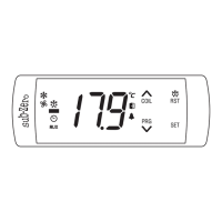
TM
SZ-7524T
Operating Instructions
L1 Parameter
22
Function: Evap. fan stop temp (Coil).
This setting is used to limit the max temperature beyond which
the Evaporator fan will cut OFF.
rS = 0.1 rS = 1
Min
Max
Fac.
Min
Max
Fac.
O
-50.0 C
O
50.0 C
O
2.0 C
O
-50 C
O
50 C
O
2 C
Example : If this parameter is set to 2.0ºC, then Evap. Fan
will cut OFF at 2.0ºC.
E6 Parameter
18
Min
Max
Fac.
Function: To set computation method for
defrost.
: Defrost Frequency time calculation will start once the
Controller is ON.
Example: If this parameter is set to 6Hrs, then defrost will
happened at every 6Hrs.
: Defrost Frequency time calculation will be done only
When Compressor is ON.
Example : If this parameter is set to 6Hrs, then after every
6Hrs of Comp. ON defrost will happen.
P9 Parameter
Min
Max
Fac.
99 Min0 Min 30 Min
21
Function : To set power ON defrost delay.
Example : If P9 parameter is 30 minutes then at power after 30
minutes defrosting will take place once.
P8 Parameter
P7 Parameter
19
Min
Max
Fac.
0 Min
99 Min
30 Min
Function: To set Defrost duration & Manual
Defrost.
Example : If P7 is set to 15 Mins, E6 is set to rEt and P8 is
set to 1 Hr then after every 1 Hr defrosting will take place for
15 mins.
This is maximum amount of time allowed for defrost. If set to
0, there will be no defrost cycle.
20
Function : To set Defrost frequency.
Min
Max
Fac.
1 Hr 31 Hrs
6 Hrs
This is the amount of time between two defrost cycles.
Example : Same as P7 parameter.
20
= Evaporator Fan will be ON /OFF independent of
Compressor Status according to Coil probe
temperature.
= Evaporator fan is OFF when compressor is OFF, and
it will be ON depending on Coil Temperature and its
set point .
L4 Parameter
25
Function: Evap. Fan differential
(hysterisis).
0
Example: If L1 parameter is set to 2.0 C, and the L4 is set to
0 0
2.0 C, then Evap. fan will cut OFF at 2.0 C and restart only at
0
0.0 C
L2 Parameter
23
Function: To set time delay between Evap.
fan relay restart time
Min
Max
Fac.
0 Min 20 Min
1 Min
Example : If this parameter sets at 3 minutes, the Evap. Fan
relay will cutoff at the temp. set by L1 parameter but the fan will
not come ON for a minimum of 3 minutes even if L4 is achieved
earlier.
L3 Parameter
24
Function: Evap. Fan operation when
compressor is OFF.
rS = 0.1 rS = 1
Min
Max
Fac.
Min
Max
Fac.
O
1.0 C
O
20.0 C
O
2.0 C
O
1 C
O
20 C
O
2 C
Min
Max
Fac.
L5 Parameter
26
Function: To set probe 2 offset calibration
(Evap. fan coil probe).
In time it may be possible that the temp. on the display may be
offset by a degree or so. To compensate for this error, you may
need to add or minus the degrees required to achieve the
0 0
correct temperature. Setting value is from -10.0 C to 10.0 C
rS = 0.1 rS = 1
Min
Max
Fac.
Min
Max
Fac.
O
-10.0 C
O
10.0 C
O
0.0 C
O
-10 C
O
10 C
O
0 C
L7 Parameter
28
Function : To set Defrost stop temperature
(Evap. coil probe)
This is the maximum temperature allowable at which the
defrost process will stop.
Defrost will stop according to P7 & E5 parameter,
whichever is achieved earlier.
rS = 0.1 rS = 1
Min
Max
Fac.
Min
Max
Fac.
O
-50.0 C
O
50.0 C
O
8.0 C
O
-50 C
O
50 C
O
8 C
L6 Parameter
27
Function: Evaporator Fan status during
defrost.
Min
Max
Fac.
= In Manual or Auto Defrost ( Hot gas or Heater ), Fan
will be OFF.
= In Manual or Auto Defrost ( Hot gas or Heater ) , Fan
will be ON.
do0
Parameter
29
Function : To activate or deactivate door
opendigital input function.
is closed.
is open.
= Door open digital input is disabled.
= Door open digital input is activated when contact
= Door open digital input is activated when contact
Min
Max
Fac.
Example : If this parameter is set to 8.0ºC, then if defrosting is
in progress then when temperature reaches 8.0ºC, the defrost
process will stop.
Suggested Wiring
Caution:Wiring for 230Vac load only
1 2
3
4
7
9
10
11 12
ROOM
COIL
DOOR
6
5
NC NONONOC
COMP
FAN
DEFROST
230VAC
50-60Hz
TO SZ-N75T
To Heater
8(3)A 250VAC max
To Fan
8(3)A 250VAC max
To Compressor
8(3)A 250VAC max
P
N
8
AUX
keys pressed simultaneously, display
will show Room Temperature.
If "nd" parameter is set to or and
+
To view coil temperature.
USER INTERFACE
UP /
Coil
Scroll through parameters & Increases
parameter value.
In Program mode:
Touch and hold for 2sec to enter into program
mode.
In program mode : Decreases parameter value
Down/
Program
In program mode: set/save the changed value
of parameter.
Set
This key will mute the visual alarm.
This key will start a manual defrost cycle if
pressed for 2 sec. Press again for 2 seconds it
will come out of defrost mode and STOP defrost
cycle.
If P7 parameter is set to 0, or Coil temp. is
greater than defrost stop temp. this key will
remain inactive.
Defrost /
Reset
Also used to check LL & LH log.
+
COMMON
*
“
“
COMMON for AUX, DOOR,
COIL, ROOM