Do you have a question about the Sungrow MVS8960-LV and is the answer not in the manual?
Specifies product applicability.
Defines intended audience and their requirements.
Provides guidance on reading and using the manual.
Explains symbols used for safety and information.
Outlines critical safety measures before and during installation.
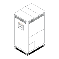
Details the physical structure, dimensions, and weight of the oil tray.
Instructions for attaching the four handles to the oil tray.
Covers the process of lifting and placing the oil tray.
Details necessary preparations before lifting the oil tray.
Provides guidance on safe and proper lifting procedures.
Explains how to correctly place the oil tray on its foundation.
Details the procedure for connecting the grounding cable.
Instructions for installing the optional oil-water separator.
Describes the process of filling the area around the oil tray with earth.
Specifies product applicability.
Defines intended audience and their requirements.
Provides guidance on reading and using the manual.
Explains symbols used for safety and information.
Outlines critical safety measures before and during installation.
Details the physical structure, dimensions, and weight of the oil tray.
Instructions for attaching the four handles to the oil tray.
Covers the process of lifting and placing the oil tray.
Details necessary preparations before lifting the oil tray.
Provides guidance on safe and proper lifting procedures.
Explains how to correctly place the oil tray on its foundation.
Details the procedure for connecting the grounding cable.
Instructions for installing the optional oil-water separator.
Describes the process of filling the area around the oil tray with earth.
This document provides a user manual for the installation of an oil tray designed for MV stations, specifically for models MVS8850-LV and MVS8960-LV. The primary function of this oil tray is to serve as a containment unit for potential oil leaks from the MV station, ensuring environmental protection and operational safety.
The oil tray acts as a secondary containment system for MV stations, particularly those utilizing oil-filled transformers. Its main purpose is to collect any transformer oil that might leak, preventing it from contaminating the surrounding environment. This is crucial for maintaining ecological integrity and complying with environmental regulations. The tray is designed to be installed in a pit on the foundation, providing a stable and secure base for the MV station. An optional oil-water separator can be integrated with the oil tray. This separator is designed to separate oil from water that may accumulate in the tray, allowing for the discharge of water while retaining the oil. This feature enhances the environmental protection capabilities of the system by preventing the discharge of contaminated water. The overall structure of the oil tray includes designated lifting points for safe and efficient hoisting, handles for easier manipulation during installation, and a mounting hole for the oil-water separator. The design emphasizes robust construction to withstand the weight of the MV station and to effectively contain oil spills.
The installation process for the oil tray is outlined with a strong emphasis on safety and precision. Before any installation, it is imperative to ensure that the product is complete and intact, with no damage to its appearance or structural components, and that the transformer has not leaked oil. Any discrepancies should be reported to Sungrow Customer Service.
While the manual primarily focuses on installation, several aspects imply maintenance considerations:
The manual emphasizes that the products and manuals are continuously improved, suggesting that future versions may include more detailed maintenance schedules or procedures. For any questions or inconsistencies, contacting Sungrow Customer Service is recommended, indicating a support structure for ongoing product maintenance and troubleshooting.
| Brand | Sungrow |
|---|---|
| Model | MVS8960-LV |
| Category | Power Supply |
| Language | English |