28
Super A2SDi-TP8F/LN4F, A2SDi-16C-TP8F User's Manual
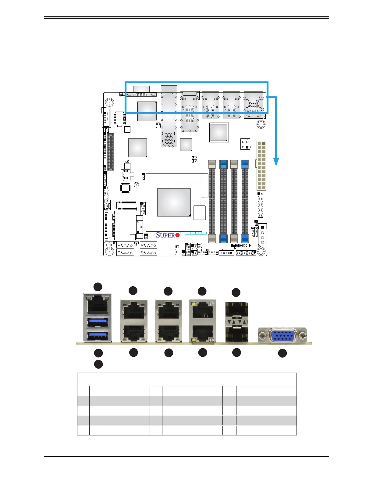
2.5 Rear I/O Ports
See Figure 2-2 below for the locations and descriptions of the various I/O ports on the rear
of the motherboard.
Figure 2-2. I/O Port Locations and Denitions
1
9
8
7
6
5
4
3
2
COM1
BIOS LICENSE
BAR CODE
A2SDi-LN4F
REV:1.02
DESIGNED IN USA
JPH1
1
JGP1
1
JBT1
JSMB1
JD1
C
A
LEDT1
C
A
LEDT3
LEDT2
A
C
LEDT4
A
C
LED1
1
JTGLED2
1
JLANLED1
1
JTGLED1
OSC1
JI2C2
1
JI2C1
1
JPTG1
JPG1
JPL1
1
JPME2
1
JWD1
JBR1
JPV1
BT1
SRW1
JL1
1
JRT3
JRT4
LED2
A
C
C
A
LEDM1
JMP1
PRESS FIT
1
JMD1
SRW4
SRW3
1
JSD1
FANA
1
FAN3
1
1
FAN1
1
FAN2
JPI2C1
I-SATA1
I-SATA0
I-SATA3
I-SATA2
JF1
1
JTPM1
JPW1
PCI-E 3.0 X4 / I-SATA
IPMI LAN
MANUFACTURING MODE
LAN7
LAN8
LAN1
LAN3
DIMMB1
DIMMB2
DIMMA2
DIMMA1
ALWAYS POPULATE DIMMx1 FIRST
Intel Atom SoC
FCBGA1310
CPU
USB4/5
USB2/3
USB0/1 (3.0)
LAN4
LAN2
LAN5
LAN6
VGA
SUPERDOM
PWR
ON
JF1
CPU SLOT7 PCI-E 3.0 X4
RST
FAIL
PS
LED
UIDNIC
2
NIC
1LED
HDD
PWR
LED
1-2:ENABLE
2-3:DISABLE
JPG1:
2-3:DISABLE
1-2:ENABLE
VGA
JPL1:
2-3:DISABLE
1-2:ENABLE
JI2C2:
1-2:ENABLE
2-3:DISABLE
JI2C1:
UID
2-3:ME
1-2:NORMAL
JPME2:
JPH1
Intel
i350-AM4
BMC
AST2400
10
12
11
Rear I/O Ports
# Description # Description # Description
1. IPMI LAN Port 5. LAN1 9. LAN5 (on TP8F)
2. USB1 6. LAN4 10. LAN8 (on TP8F)
3. USB0 7. LAN2 11. LAN7 (on TP8F)
4. LAN3 8. LAN6 (on TP8F) 12. VGA

 Loading...


