3. SETTINGS AND ADJUSTMENTS
28
3.5 Connection Examples of Various
Systems
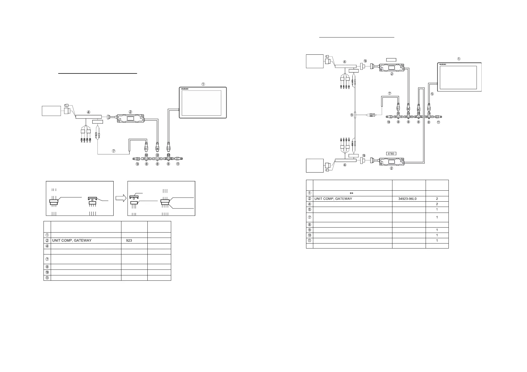
3.5.1 Connection of Mechanical Remote Control System
The single station of single engine
No.
Part Names
Part No.
Additional
Quantity
34 -96L0
1
36661-96L3
1
HARNESS ASSY, NETWORK
POWER
36663-88L0
1
CONNECTOR COMP, BRANCH
36664-88L0
UNIT COMP, RESISTOR FEMALE
36665-88L0
1
UNIT COMP, RESISTOR MALE
36665-88L1
1
MAIN WIRING
HARNESS
12
NMEA PWR
GAUGE
CONNECTOR
*2 SDS CONNECTOR (DF40A-)
DIGITAL GAUGE DIAGRAM
SDS
CONNECTOR
SDS
CONNECTOR
CAP
CAP
GAUGE
CONNECTOR
GAUGE
CONNECTOR
R
B
L
B
G/W
P/W
L/B
G/W
P/W
L/B
G/W
P/W
L/B
Y
B/L
Or/Y
B
Y
B/L
Or/Y
B
G/W
P/W
L/B
1
ADAPTER COMP, GAUGE
1
յ
WIRE COMP, EXTENSION (0.6 m)
36662-88L1
յ
34900-98L
DISPLAY ASSY,MULTI* *
*1
*1: Connect only the system with the trim sender.
*2: It is required to change the SCS connector to one for engine.
Remove the SDs connector cap to connet to the gauge connector, and connect
the DS connector to the female gauge connector.
*3: With CONNECTOR COMP, BRANCH : Q'ty. 1
36663-88L2
*3
3
3. SETTINGS AND ADJUSTMENTS
29
The single station of dual engine
No.
Part Names
Part No.
Additional
Quantity
ADAPTER COMP, GAUGE
36661-96L3
HARNESS ASSY, NETWORK
POWER
36663-88L0
CONNECTOR COMP, BRANCH
36664-88L0
4
ADAPTER, GAUGE FOR MULTI
36665-87L1
UNIT COMP, RESISTOR FEMALE
36665-88L0
UNIT COMP, RESISTOR MALE
36665-88L1
1
WIRE COMP, EXTENSION (0.6 m)
36662-88L1
34900-98L
DISPLAY ASSY,MULTI
ր
WIRE COMP, DUAL GAUGE EXT (0.6 m)
36667-96L2
–
*1: Connect only the system with the trim sender.
*3: With CONNECTOR COMP, BRANCH : Q'ty 1
*4:
⑯
WIRE COMP, DUAL GAUGE EXT (0.6m) Option.
36663-88L2
NMEAPWR
NMEAPWR
MAINWIRING
HARNESS
(PORT)
MAINWIRING
HARNESS
(STBD)
12
12
R
B
L
B
R
B
L
B
PORT
*1
*4
*1
*4
*4
*3
 Loading...