Position
Explanation
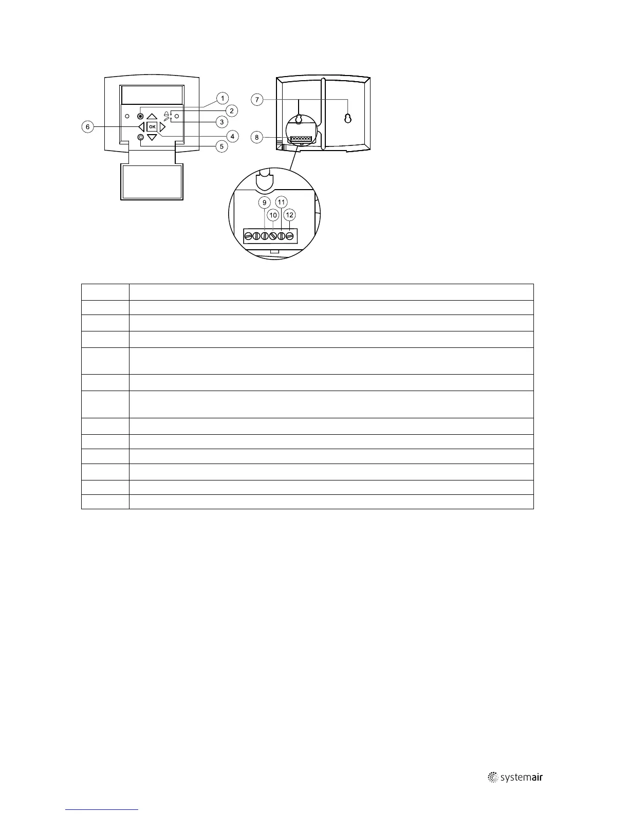
1
Alarm button: Gives access to the alarm list.
2
Alarm LED: Indicates alarm by flashing red light.
3
Write LED: Indicates by flashing yellow light that parameters can be set or changed.
4
OK button: Press this button to be able to change or set parameters whenever possible. Also used to
move between changeable parameters in one dialogue window frame.
5
Cancel button: Used to abort a change and return to the initial setting.
6
Right/Left & Up/Down buttons: Used to move up, down, left & right in the menu tree. Up/Down buttons
are also used to increase or decrease values when setting or changing parameters.
7
Mounting holes.
8
Connection block.
9
Connection to brown cable.
10
Connection to yellow cable.
11
Connection to white cable.
12
Connection to black cable.
3.1.2 Navigating the menus
The start display (the display normally shown) is at the root of the menu tree. Pressing DOWN will move you through
the menu options. UP will move you back through the options. To enter a higher menu level, use UP or DOWN to place
the cursor at the menu you wish to access and press RIGHT. If you have sufficient log on privileges the display will
change to the menu you have chosen.
At each level there may be several new menus which you move through using UP/DOWN. Sometimes there are further
sub menus linked to a menu or menu item. This is indicated by an arrow symbol at the right-hand side of the display. To
enter a menu, press RIGHT again. To step back to previous menu level, use LEFT.
4 Commissioning
4.1 Before starting the system
When the installation is finished, check that:
• The unit is installed in accordance with the installation instructions
• The unit is correctly wired
• Sound attenuators are installed and that the duct system is correctly connected to the unit
124455 | A003

 Loading...