6
| Product description
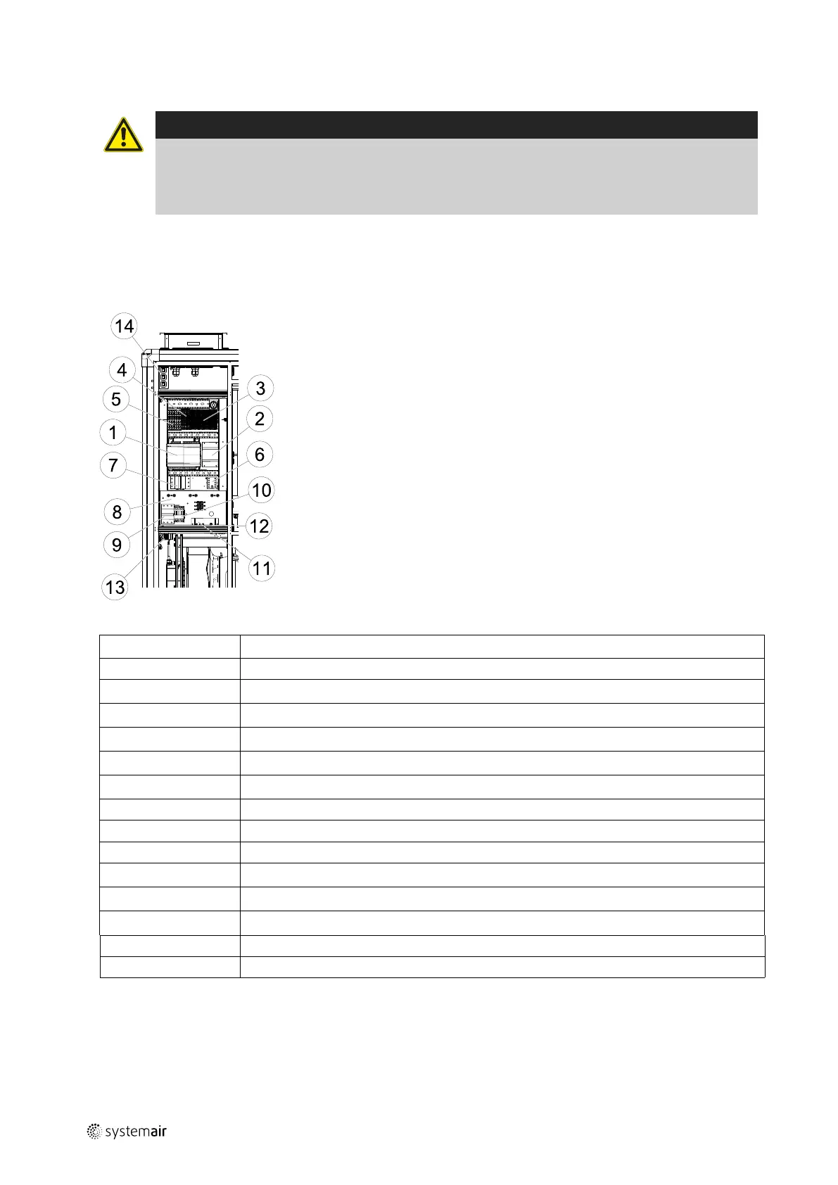
2.4 Internal components electrical connection box
Danger
• Make sure that the mains to the unit is disconnected before performing any maintenance or electrical
work!
• All electrical connections must be carried out by an authorized installer and in accordance with local rules
and regulations.
Topvex SR/TR 03-06 are equipped with a built in regulator and internal wiring (figure 4).
The figure shows the electrical connection box for the Topvex TR 03-06 units. The connection box for the Topvex SR
03-06 has the same layout and components with the difference that the electrical heater is situated in a separate
compartment.
Fig. 4 Electric components
Position
Description
1
Control unit CU283W-4
2
Transformer 230/24V AC
3
Terminals for internal and external components
4
Terminals for internal wiring
5
Terminals for mains supply to the unit
6
Contactor (K2) Pump control water (HW units only, not present in EL-units)
7
Automatic fuse
8
Electric heater frame
9
Automatic fuse for heater
10
Contactor (K3) for control of EL heater
11
Thermostat (EL units)
12
Manual over heat protection reset (EL units)
13
Switch module
14
Panel outlet
151618 | A002
 Loading...