_____________________________________________________________________________________________________
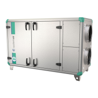
Topvex TR03, TR04, TR06 Installation description
205354 Systemair AB
13
NOTE!
Do not connect tumble dryers to the ventilation system.
Duct connections/duct ends should be covered during storage and installation.
Grilles for discharge/roof units must be installed according to building regulations in
force.
Duct connections
Secure all joints between ducting and the Topvex unit accurately using a minimum of 4 rivets per joint
(circular ducts) and 4 M8 bolts per joint (rectangular ducts). Rectangular ducts need sealing strips or
sealing compound to ensure the air tightness.
Attention
To avoid fan noise being transferred via the ducting system, silencers should be installed both on
supply and extract air.
Condensation/heat insulation.
Outdoor air duct and discharge ducts must always be well insulated against condensation. Correct
insulation installation on ducts connected to the unit is especially important. All ducting installed in
cold rooms/areas must be well insulated. Use insulating covering (we recommend a minimum of 100
mm mineral wool) with plastic diffusion barrier.
In areas with extremely low outdoor temperatures during the winter, additional insulation must be
installed. Total insulation thickness must be at least 150 mm.
NOTE! If the unit is installed in a cold place make sure that all joints are covered with
insulation, and tape well.
Electrical connection
The unit must not be put into operation before all the electrical safety precautions have been read and
understood.
See fig. 3 where to find the safety switch and electrical connection box.
See page 1 and the attached wiring diagram how to connect the electrical cables.
TOPVEX has electric supply through a lockable safety switch on top of the unit. All units except for
Topvex TR03 HW are to be connected to a 400V 3~ alt. 230V 3~ power supply (the heater in TR03
EL can be reconnected to 230V 3~). Topvex TR03 HW needs a 230V 1~ supply. TR04 and TR06
have separate models for 230V 3~ power supply. The unit is designed for continuous operation and
permanent connection to the mains.
Power consumption
TOPVEX TR03 EL 400V 3N~ TOPVEX TR03 EL 230V 3~ TOPVEX TR03 HW 230V 1~
Fans: 1010 W total Fans: 1010 W total Fans: 1010 W total
El heating battery: 3 kW (EL) El heating battery: 3 kW (EL) El heating battery: -
Fuse:16A Fuse:16A Fuse: 10A
TOPVEX TR04 EL/HW 400V 3N~ TOPVEX TR04 EL/HW 230V 3~
Fans: 2176 W total Fans: 2176 W total
El heating battery: 3.99 kW El heating battery: 3.99 kW
Fuse: 10A (HW) & 13A (EL) Fuse: 10A (HW), 20A ( EL)
TOPVEX TR06 EL/HW 400V 3N~ TOPVEX TR06 EL/HW 230V 3~
Fans: 2010 W total Fans: 2202 W total
El heating battery: 6.3 kW El heating battery: 6.3 kW
Fuse: 10A (HW), 16A (EL) Fuse: 10A (HW), 25A (EL)
 Loading...