17
Topvex FC
Compact Air Handling Unit
Operation and Maintenance Instructions
Document in original language
125918-EN_GB
2015-03-16 A001
Operation and Maintenance Instructions
Systemair AB
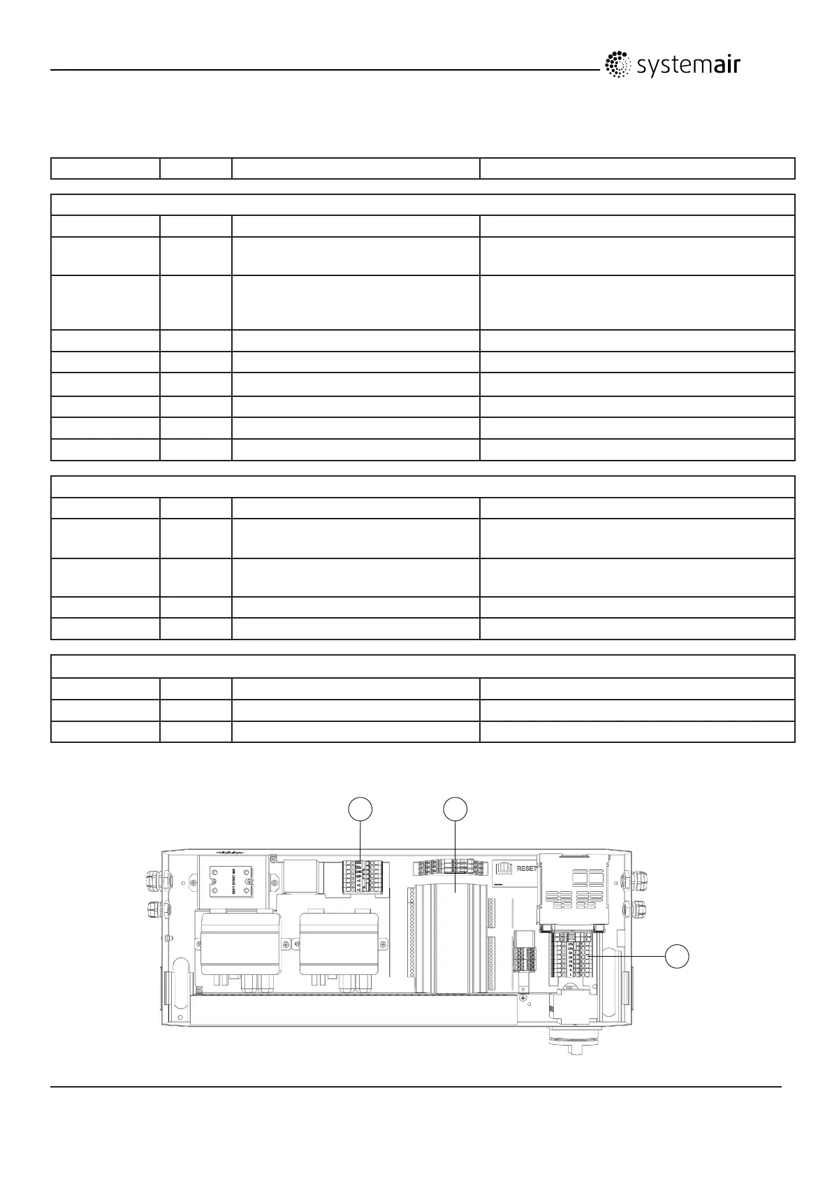
3.5.5 External connections
Terminal block Description Remark
Main terminals - 1
PE PE Ground
N N Earthed neutral (mains power supply) Used for phase 230V 1~ and
400V 3~
L1 L1 Phase (mains power supply) Used for phase 230V 1~ if the
unit has this mains
400V 3~
L2 L2 Phase (mains power supply) 400V 3~
L3 L3 Phase (mains power supply) 400V 3~
Lfs Lfs Damper supply (230V output) 230V output
Lfe Lfe Damper exhaust (230V output) 230V output
Err 14 - DO4 Error output (230V) 230V Output
Lout Lout Phase for accessories (230V output) 230V output (2A)
Terminals for external components - 2
+C 4 - +C Terminals for external control inputs External control, Fire, Occupancy
0-10V VALVE * 93 - A03 Control signal valve actuator, Water
Heating
0-10V DC
+24V +24V Power supply for accesories (AQS,
actuators)
24V DC
GND GND Ground terminal (AQS, actuators) GND
GDo 10 - GDo Terminal for internal components GDo
Regulator E-28 - 3
DI1 71 - DI1 External control contact NC contact
DI2 72 - DI2 Fire contact NC contact
DI3 73 - DI3 Occupancy contact NC contact
* Avalible only for VSC 700 HW, VSC 1500 HW, VSC 2000 HW
Connections to external functions:
2 3
1
 Loading...