5-4
USER INTERFACE
085592-M
User Interface
5
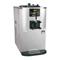
Feed Tube
The feed tube maintains overrun and allows enough mix
to enter the freezing cylinder after a draw. One end of the
tube has a mix delivery hole on the side, and the other
end does not.
Figure 5-3
The feed tube serves two purposes.
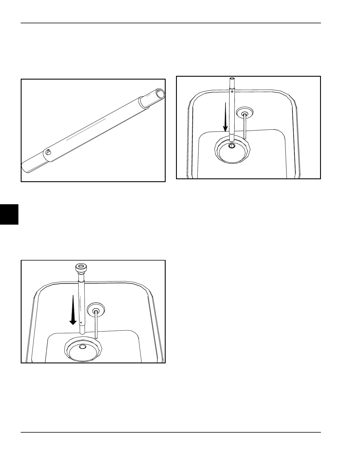
• Normal Operation: After priming the machine, the
end of the feed tube with the mix delivery hole is
placed in the mix inlet hole, and the air orifice is
installed. Every time the draw handle is raised, new
mix and air from the hopper will flow down into the
freezing cylinder. This will keep the freezing cylinder
properly loaded and will maintain overrun.
Figure 5-4 Feed Tube Position during Normal Operation
• Standby Operation: During long “no sale” periods,
the air orifice is removed and the feed tube is
inverted. The end of the feed tube without the mix
delivery hole is placed in the mix inlet hole to prevent
mix from entering the freezing cylinder.
Figure 5-5 Feed Tube Position during Standby Operation
Note: Make sure the level of mix is below the mix
delivery hole in the side of the feed tube. Failure to follow
this instruction may result in lower product quality when
normal operation is resumed.
 Loading...