Factory Alignment Specification of normal SIACP
Page 6 of 12
upgrade FLASH SW from USB”.
Remenber to do “Reset all” after upgrade the SW.
1.3 Project ID check and modify
There is different ID stored in the NVM depended on different Panels. Modify it with Hyper
terminal if the initial ID or a wrong ID make the set can not display clearly. See Appendix
. It can
be checked and modified in Factory menu->Project info->Project ID if the set can display
clearly . The set should be restart if the project ID is changed .
1.4 Functional Test
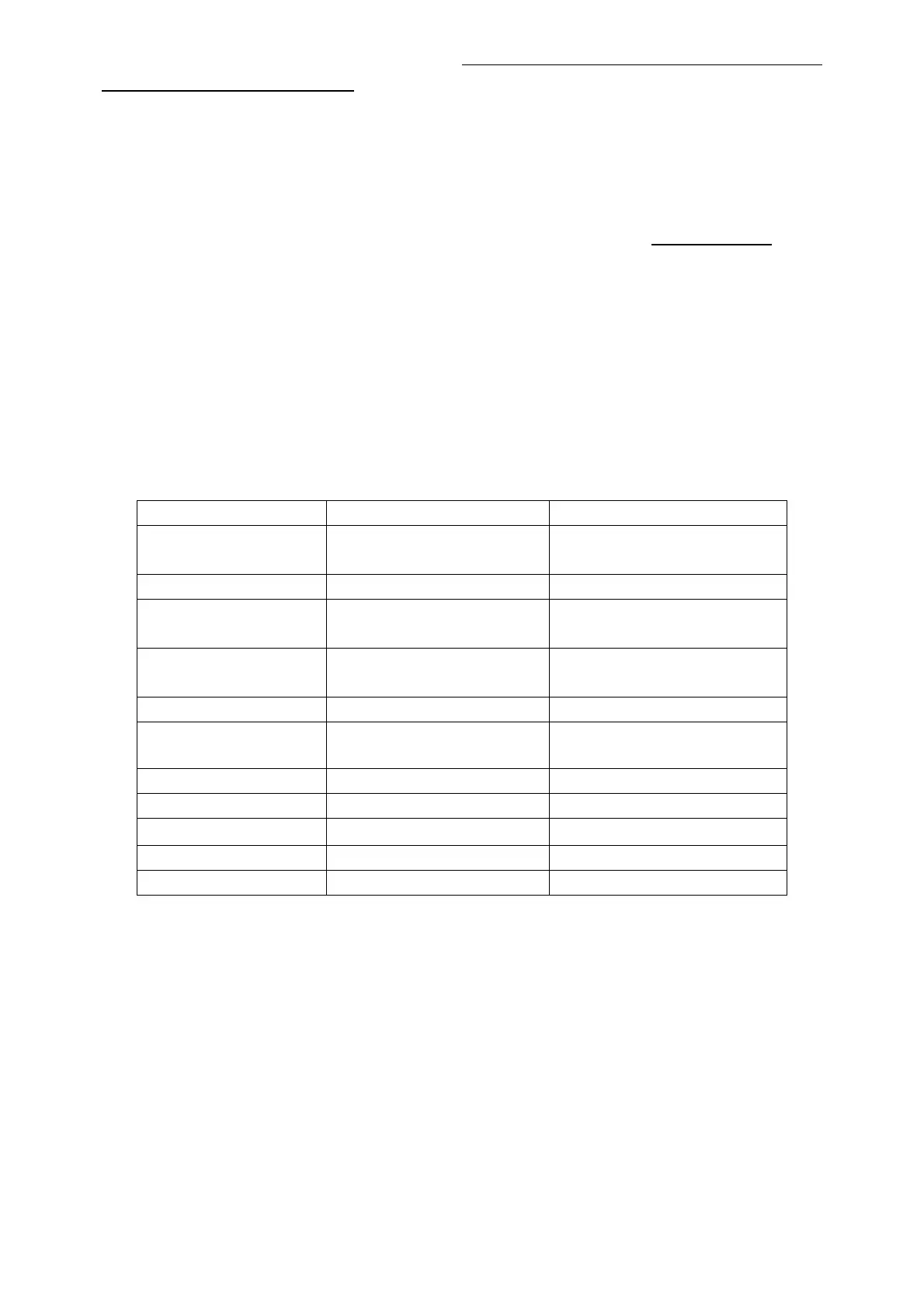
Once the boards (chassis, KB, IR, PSU…) and the panel are well interconnected, connect all
external generator devices to relevant inputs/outputs below according to their respective test
patterns format and check picture content and sound quality accordingly
:
Source Test signal (generator) Test pattern (format/image)
Analog /Digital Tuner RF cable Full Band (VHF/UHF) + CATV
SBTVD-T
Composite(CVBS) Chroma/Fluke PAL Half Color & Gray bars
VGA Chroma/QuantumData 1024x768@60Hz
Half Color & Gray bars
CMP (YPrPb) Chroma/QuantumData 1080i@60Hz
Half Color & Gray bars
HDMI DVD with HDMI compliancy Movie 720p@60Hz
Headphone RF cable First channel
Loud Speakers RF cable First channel
USB USB device Picture musica Video
Audio tones can be defined by the factory (ie: 1KHz & 3KHz, sweep, …).
Picture video formats can be changed by the factory according to their own standard.
1.5 DDC & EDID Test
The E-EDID data structure are according to VESA Enhanced EDID 1.3 (and EIA/CEA-861B for
HDMI).
HDMI have their own separate bin files:
For EDID check, it’s needed to check whether the correct EDID is downloaded by checking
corresponding EDID NVM Checksum or read them out to check bit by bit if it is in line with the
released EDID bin file.
 Loading...