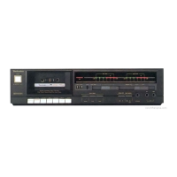
RS-B555
Mi
CONTENTS
Page
Page
SAFETY
PRECAUTION
...........:csscssccssesecsssessceseneeeessesenesenseeeseenee
2
SCHEMATIC
DIAGRAM
...........:.:sscssssssessessssssseeeseeeersees
19~26
ACCESSORIES
6
sccsscccccssccsseccd
eich
sais
ticret
eet
caneavene
ca
cvanncenticns
2
TROUBLESHOOTING
OF
DIRECT
DRIVE
MOTOR............
26
FRONT
PANEL
CONTROLS
AND
FUNCTIONS...
.
3,4
TERMINAL
GUIDE
OF
IC’S,
RECORDING
WITH
HIGH
TONE
QUALITY................cccceeeee
5
TRANSISTORS
AND
DIODES.
............cccssssseeceseseeeetenseeeeeee
27
OUTLINE
OF
THE
DIRECT
DRIVE
MOTOR
SYSTEM...........
6
PRINTED
CIRCUIT
BOARDG..............
.
28~32
CONNECTIONS
wecscstscievessesvacsndvoncsseaiscesabcsccescossesslecssorvivecencetonss
6
WIRING
CONNECTION
DIAGRAM
.............::scscsssseesssseseesees
33
DISASSEMBLY
INSTRUCTIONG.
............cccccsssssesseeeeeeeees
7~10
REPLACEMENT
PARTS
LIST
MEASUREMENT
AND
ADJUSTMENT
METHODES....
11~13
EXPLODED
VIEWS.
..........:ccccsscssssessessccesersseesesseesetseteeees
TERMINAL
FUNCTION
OF
IC’S....0......eesseseceseeeeeereees
14,
15
REPLACEMENT
PARTS
LIST
BLOCK
DIAGRAM.........ccsssscssssescsnes
«=
16,17
RESISTORS
&
CAPACITORS
INTERNAL
CONNECTION
OF
EFL..........0cccssssssssessseeeeneseees
18
PACKING.......cccsesssssensscereseeeneee
TECHNICAL
INFORMATION
Mm
SAFETY
PRECAUTION
(this
“safety
precaution”
is
applied
only
in
U.S.A.)
.
Before
servicing,
unplug
the
power
cord
to
prevent
an
electric
shock.
When
replacing
parts,
use
only
manufacturer’s
recommended
components
for
safety.
.
Check
the
condition
of
the
power
cord.
Replace
if
wear
or
damage
is
evident.
.
After
servicing,
be
sure
to
restore
the
lead
dress,
insulation
barriers,
insulation
papers,
shields,
etc.
Before
returning
the
serviced
equipment
to
the
customer,
be
sure
to
make
the
following
insulation
resistance
test
to
prevent
the
customer
from
being
exposed
to
a
shock
hazard.
ORWN>
e
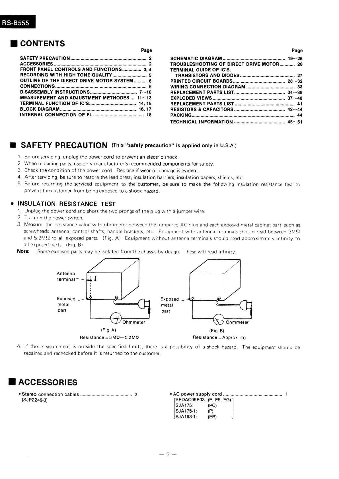
INSULATION
RESISTANCE
TEST
1.
Unplug
the
power
cord
and
short
the
two
prongs
of
the
plug
with
a
jumper
wire.
2.
Turn
on
the
power
switch.
3.
Measure
the
resistance
value
with
ohmmeter
between
the
jumpered
AC
plug
and
each
exposed
metal
cabinet
part,
such
as
screwheads
antenna,
control
shafts,
handle
brackets,
etc.
Equipment
with
antenna
terminals
should
read
between
3MQ
and
5.2MQ
to
all
exposed
parts.
(Fig.
A)
Equipment
without
antenna
terminals
should
read
approximately
infinity
to
all
exposed
parts.
(Fig.
B)
Note:
Some
exposed
parts
may
be
isolated
from
the
chassis
by
design.
These
will
read
infinity.
Antenna
terminal
Exposed
Exposed
metal
metal
part
part
Ohmmeter
Ohmmeter
(Fig.
A)
(Fig.
B)
Resistance
=
3M2—5.2MQ
Resistance
=
Approx
oo
4.
If
the
measurement
is
outside
the
specified
limits,
there
is
a
possibility
of
a
shock
hazard.
The
equipment
should
be
repaired
and
rechecked
before
it
is
returned
to
the
customer.
Mi
ACCESSORIES
©
Stereo
CONNECTION
CADIES
00...
eeeeseeeecsseseeeseeseee
2
©
AC
Power
SUPPLY
COM
.u....
eee
eesececcesseeeseeseeseeeaneeesees
1
[SJP2249-3]
SFDACO5E03:
(E,
E5,
EG)
SJA175:
(PC)
SJA175-1:
—
(P)
SJA193-1:
(EB)
 Loading...