SA-EX310
Operation Checks and Main Component Replacement Procedures
"ATTENTION SERVICER" Some chassis components may have sharp edges. Be careful when disassembling and servic-
ing. Please take note that the diagrams shown are for model SA-EX510 which is similar to SA-
EX310.
1. This section describes procedures for checking the operation of the major printed circuit boards and
replacing the main components.
2. For reassembly after operation checks or replacement, reverse the respective procedures.
Special reassembly procedures are described only when required.
3. Select items from the following index when checks or replacement are required.
Checking Procedure For Each Major P.C.B ........................................................................................ 4 ~ 6
Main Component Replacement Procedures ........................................................................................ 6 ~ 8
Contents
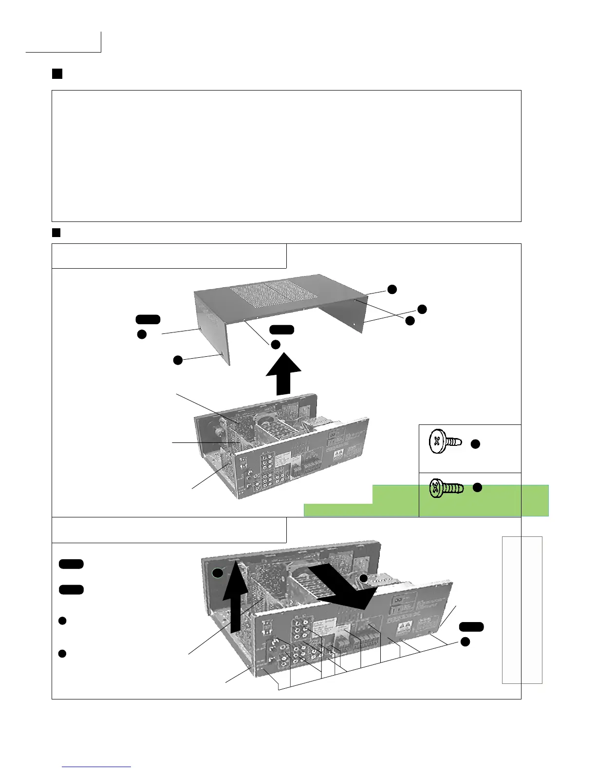
Checking Procedure For Each Major P.C.B.
1. Checking of the Panel P.C.B., and Tuner P.C.B.
a
X
4
a
a
a
b
b
Step 2
X
2
PANEL P.C.B.
(Solder Side)
IN/OUT TERMINAL P.C.B.
(Solder Side)
Step 1
Remove the top cabinet.
TUNER P.C.B.
(Solder Side)
[XTBS3+8JFZ1] (Black)
b
[SNE2129-1] (Black)
a
2. Checking of the In/Out Terminal P.C.B.
b
Step 2
X 14
Step 3
Release the catch, pull
the rear panel in the
direction of arrow 1 and
simultaniously remove the
In/Out Terminal P.C.B. in
the direction of arrow 2
.
1
2
Step 1
Catch
Catch
IN/OUT TERMINAL
P.C.B.
 Loading...