EasyManua.ls Logo

Technics SE-A100 Service Manual

Technics SE-A100
28 pages
To Next Page IconTo Next Page
To Previous Page IconTo Previous Page
Page #13 background image
Question and Answer IconNeed help?

Do you have a question about the Technics SE-A100 and is the answer not in the manual?

Technics SE-A100 Specifications

General IconGeneral
BrandTechnics
ModelSE-A100
CategoryAmplifier
LanguageEnglish

Summary

SPECIFICATIONS (IHF '78)

AMPLIFIER SECTION

Detailed technical specifications for the amplifier section, including power output and distortion.

GENERAL

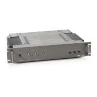
General specifications like power consumption, power supply, dimensions, and weight.

SAFETY PRECAUTION

INSULATION RESISTANCE TEST

Procedure for performing an insulation resistance test to ensure user safety.

Class AA Circuit Technology Explanation

Background of Class AA Circuit Development

Discusses the development background of the "class AA" circuit technology and its advantages.

Class AA Operation Principle

Bridge Circuit Design

SE-A100 Amplifier Circuit Description

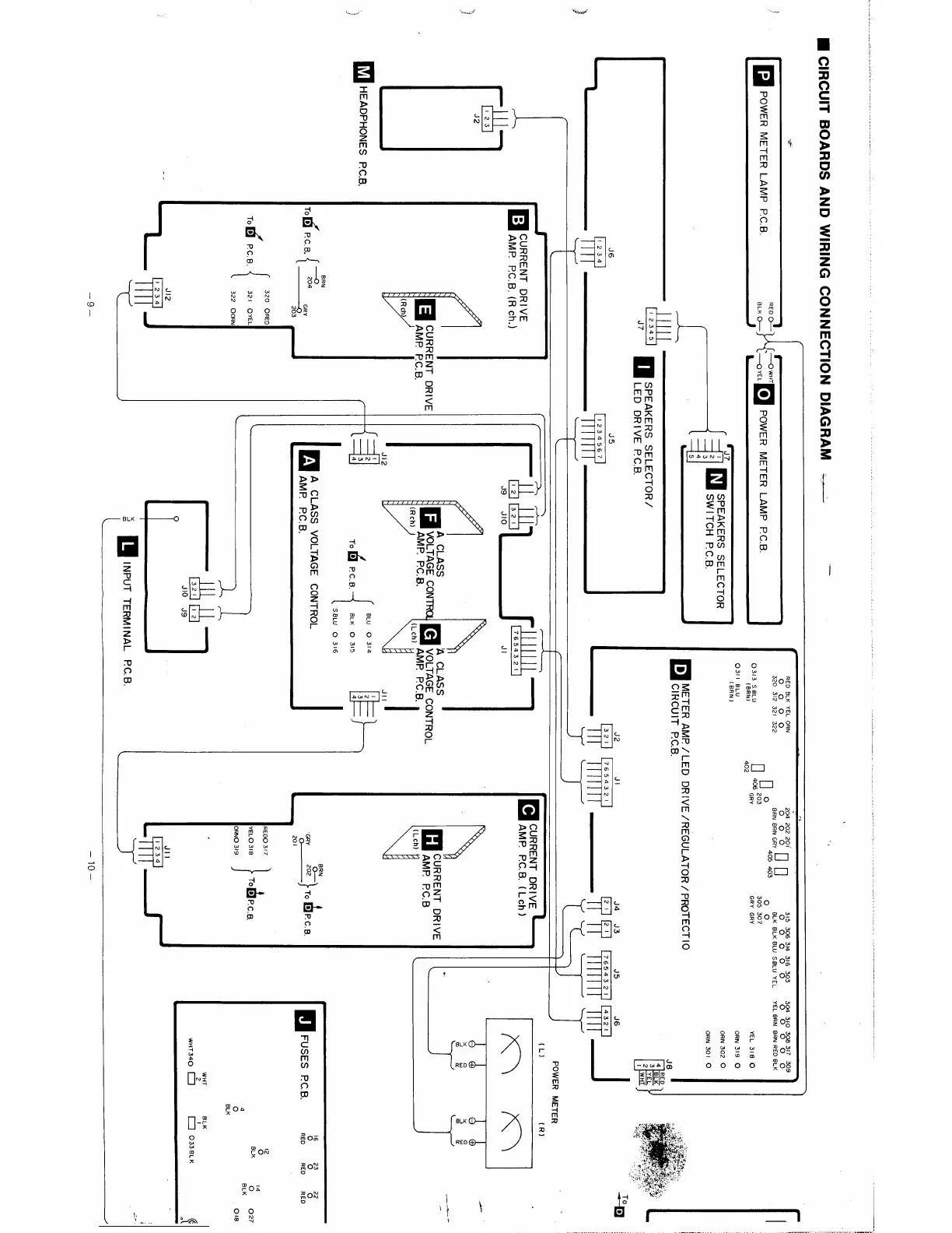
Describes the current drive amplifier circuit and its components like the output stage and power source.

Service Hints and Procedures

Check Procedure for Output Signal Issues

Step-by-step procedure for diagnosing issues with no or distorted output signals.

Product Features

VC4 Amplifier Composition and Class AA

Explains the VC4 amplifier composition and its benefits for sound quality.

Premium Design and Furnishings

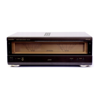
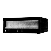
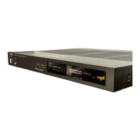
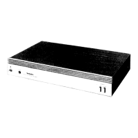
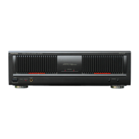
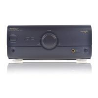
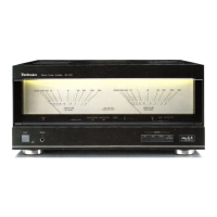
Describes the premium design and construction features of the amplifier.

Location of Controls

Disassembly Instructions

Pre-Repair Preparation

MEASUREMENTS AND ADJUSTMENTS

Amplifier Adjustments

Voltage Control Amp Idling Adjustment

Procedure for adjusting the idling current of the voltage control amplifier.

Current Drive Amp Idling Adjustment

Procedure for adjusting the idling current of the current drive amplifier.

Bridge Balance Adjustment

Instructions for adjusting the bridge balance of the amplifier circuit.

Operational Checks and Adjustments

Power Meter Adjustment

Steps to calibrate and adjust the power meter to indicate correctly.

Muting Circuit Operation Check

Procedure to verify the correct operation of the muting circuit during power transitions.

Overload and Protection Circuit Test

How to test the overload detection and protection circuit functionality.

Circuit Board and Wiring Diagram

Printed Circuit Board Layouts

Component Identification Guide

System Block Diagram

Schematic Diagrams

Protection Circuitry and Indicators

Protection Circuit Explanation

Explains the protection circuit operation and its indicators.

Operation Indicator Guide

Describes the meaning and behavior of the unit's operation indicators.

Replacement Parts List

Exploded Views for Service

Related product manuals