Do you have a question about the Technics SL-PS50 and is the answer not in the manual?
| Type | CD Player |
|---|---|
| Disc format | CD |
| Channels | 2 |
| Frequency Response | 2 Hz to 20 kHz |
| Signal-to-Noise Ratio | 106 dB |
| Dynamic range | 96 dB |
| Total harmonic distortion | 0.003% |
| Digital converter | 1-bit DAC |
| Output Level | 2.0V |
| Digital outputs | coaxial |
| Dimensions | 430 x 310 x 100 mm |
Detailed audio output and response parameters.
Laser pickup wavelength and performance specifications.
Power supply, dimensions, and weight details.
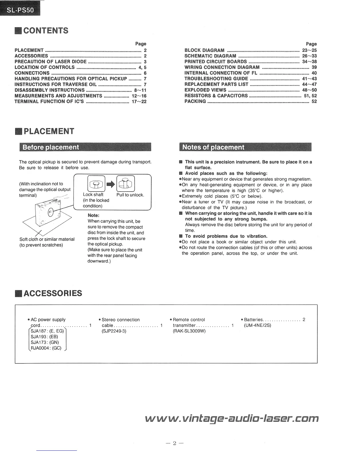
Instructions for optimal unit placement and environmental considerations.
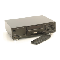
List of items provided with the CD player.
Critical safety information regarding laser diode exposure and handling.
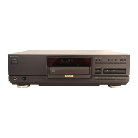
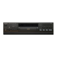
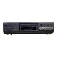
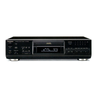
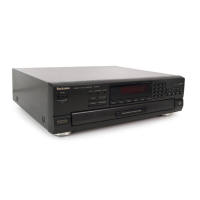
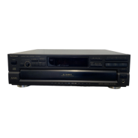
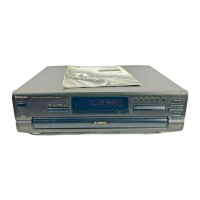
Identification and function of front panel buttons and indicators.
Explanation of buttons and indicators on the remote transmitter.
Diagram and instructions for connecting audio output and power.
Precautions against static discharge and physical shock to the pickup.
Step-by-step guide for applying lubricant to the traverse mechanism.
Procedures for removing cabinet, front panel, and related parts.
Detailed steps for removing internal circuit boards (FL, Timer, Headphones, Operation).
Steps for removing disc holder, loading base, and servo P.C.B.
Procedures for removing the optical pickup and spindle motor.
Steps to prepare the unit for calibration and identify adjustment points.
Setting turntable height and aligning RF signal for optimal playback.
Adjusting focus, tracking gain, and PD balance for servo performance.
Fine-tuning focus, tracking offset, and balance for servo accuracy.
Verifying playback functions after calibration procedures.
Pin definitions for servo amplifier and processor ICs.
Pin details for system control, DSP, and drive ICs.
Pin functions for digital filter and D/A converter ICs.
Overall functional block representation of the CD player.
Detailed electrical schematics for various circuits.
Visual guides showing component placement on circuit boards.
Diagram illustrating internal cable and connector routing.
Details on connecting the FL display elements and pinout.
Flowchart for verifying normal playback operation sequences.
Diagnostic charts for identifying operational failures.
List of part numbers for replacement components.
Diagrams showing component assemblies for repair.
Table listing values and reference numbers for passive components.
Guidelines for packaging the unit for shipment or storage.