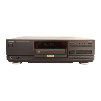
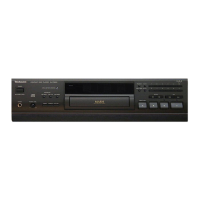
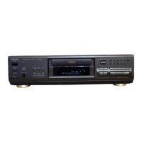
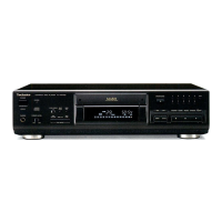
_SL-PS900
Mi
CONTENTS
Page
BEFORE:
USE
occ
csccicscscscsstseceseisecsswonssnsceecntccecscssvnscvocetsencsecescstactions
2
ACCESSORIES.
....cscsscssssssssectsnsccssseresennanes
4
BEFORE
TRANSPORTING
THE
UNIT..........ccccsssccsssssscsssecesassseos
2
PRECAUTION
OF
LASER
DIODE
..........-.ccssecssssecsssssssareeseseresees
3
PLACEMENT
......ccccccescseceseveseesecenserees
4
CONNECTIONS.
........c.ccssecssscsssecessorconsenessusterecsscssansnsversenesecaserensrses
4
LOCATION
OF
CONTROLS
........cccssssesosseoeecessssesesszeees
oe
ST
HANDLING
PRECAUTIONS
FOR
OPTICAL
PICKUP.
...............
8
INSTRUCTIONS
FOR
TRAVERSE
OIL
.u......cscccsssssncesteseerasneaeaee
8
DISASSEMBLY
INSTRUCTIONS
...........ssscssssccersessssescorssnses
9~14
MEASUREMENTS
AND
ADJUSTMENTS
.....
15~17
TERMINAL
FUNCTION
OF
IC’S.............025
-
18~23
DIGITAL
SERVO
SYSTEM
........s:ssscssscsesccssssesssssessererssenenesse
24,
25
Mi
BEFORE
USE
Be
sure
to
disconnect
the
mains
cord
before
adjusting
the
voltage
selector.
Use
a
minus
(—)
screwdriver
to
set
the
voltage
selector
(on-the
rear
panel)
to
the
voltage
setting
for
the
area
in
which
the
unit
will
be
used.
AC
power
supply
e@Siereo
connection
Remote
control
COM:
2.3.
con
edar
aan
cee
1
pe.
Cable
........
eee
wee
1
pe.
transmitter
..............
1
pe.
(SFDACOSE03):
(E,
EG)
(SJP2249-4)
(RAK-SL512W)
Note:
The
configuration
of
the
AC
power
supply
cord
differs
according
to
area.
(SJA193):
(EB)
(RJA0004):
(GC,
PX)
(SJA173):
(GN)
eBatteries
................
2
pcs.
(UM-4NE/2S)
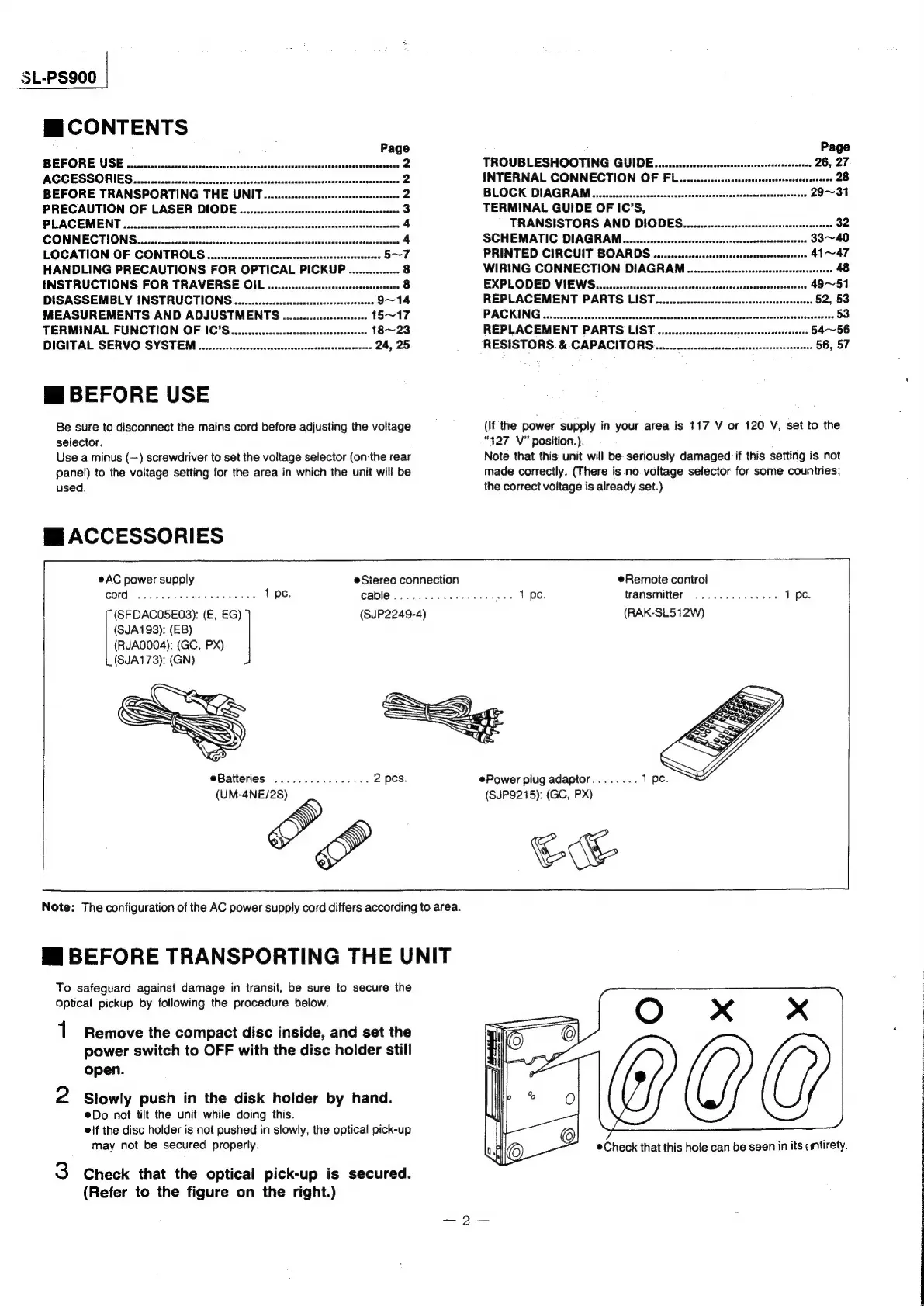
Mi
BEFORE
TRANSPORTING
THE
UNIT
To
safeguard
against
damage
in
transit,
be
sure
to
secure
the
Optical
pickup
by
following
the
procedure
below.
1
2
Remove
the
compact
disc
inside,
and
set
the
power
switch
to
OFF
with
the
disc
holder
still
open.
Slowly
push
in
the
disk
holder
by
hand.
Do
not
tilt
the
unit
while
doing
this.
eif
the
disc
holder
is
not
pushed
in
slowly,
the
optical
pick-up
may
not
be
secured
properly.
Check
that
the
optical
pick-up
is
secured.
(Refer
to
the
figure
on
the
right.)
TROUBLESHOOTING
GUIDE..........sssccscenssssssseresrsensarsessones
INTERNAL
CONNECTION
OF
FL
BLOCK
DIAGRAM........csccsssscsssssasssssssnssssseesecaessseananacenorsass
TERMINAL
GUIDE
OF
IC’S,
TRANSISTORS
AND
DIODEG.........csccscscsesescrscersesersssnerstees
32
SCHEMATIC
DIAGRAM
a
PRINTED
CIRCUIT
BOARDS
............cccssssssnesesesentesesesenteens
41~47
WIRING
CONNECTION
DIAGRAM...........sssscesssscenesensnenevsrsesnens
48
EXPLODED
VIEWG.........ccssccscessrsrerene
REPLACEMENT
PARTS
LIST
PACKING
.......ccscsscssessnseresserseeee
REPLACEMENT
PARTS
LIST...
RESISTORS
.&
CAPACITORS
(If
the
power
supply
in
your
area
is
117
V
or
120
V,
set
to
the
“427
V”
position.)
Note
that
this:
unit
will
be:
seriously
damaged
if
this
setting
is
not
made
correctly.
(There
is.no.
voltage
selector
for
some
countries;
the
correct
voitage
is
already
set.)
Power
piug
adaptor
(SJP9215):
(GC,
PX)
Gwe
®Check
that
this
hole
can
be
seen
in
its
entirety.
 Loading...