We
want
to thank
you
f
or selecting the
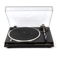
SL-Q3.
For optimum
performance,
we recommend
that
you
read these instructions
caref ully
Before
use
Caution:
Never
connect
the
AC
power plug
before assembly
has been
completed
Attach
the dust cover
iast,
so
that assembly
and adjustments
can
be made
most conveniently
I
Checklist
ol
parts
Turntable
unit
Turntable
platter.
Turntablemat...
Dust cover
45-rpm
adapto( .. . . .
Balanceweight..
...
Headshe
I I
Overhang
gauge
r
Adjustment
ol overhang (See
Fig.
5.)
1 lnsert the headshell into the
gauge
2 Loosen the mounting
screws
and move
the cartridge for-
ward or backward
untilthe stylus tip lines up with theedge
of the
gauge
3 Tighten the mounting screws without
moving the car
tridge
Note:
Your
cartridge
is now adjusted
for
lowest
tracking error
and
minimum distortion
This
gauge
is
exclusively designed for
thrs tonearm
lnstallalion of
headshell(See
Fig. 6.)
lnsert the
headshell into the f ront
end of
the tubular
arm, and
turn the
lo.cking nut clockwise
(in
the
direction
shown by the
arrow
"A"),
with the
headshell iirmly held
horizontally
lnstallation ol
balance weight
(See
Fig. 7.)
Place
the
balance weight
on the rear shalt of the tonearm
Adjustments of
horizontal
zero
(0)
balance and
stylus
pressure
1
Remove
the stylus
protector,
if
your
cartridge
has
a detach-
able
one
Be
careful
not to touch your
fingers
to the
stylus
tip
Release the arm
clamp and
liit
the tonearm
from
the arm
rest to
free
it
Turn the entire
balance
weight
clockwise
(indicated
by
the arrow
"A")
orcounterclockwise
(indicated
by the arrow
"8")
until the tonearm is
approximately
balanced
horrzon-
tally
(f
loats
f reely) (See
Figs.
8 and
9.)
Note:
Fig.
9-1
Excessive forward
advancement
of
the
balance
weight
causes the cartridge
side to be lowered
Fig.
9-2
Excessive backward
retreatment
of the
balance
weight
causes
the cartridge
side to be raised
Fig.
9-3
Upon balancing between
the balance
weight
and
car-
tridge,
the tonearm is held
horizontal
During
the
adjustment
of
the horizontal
zero (0)
balance,
be careful
that the stylus tip
ol the cartridge
does not
contact the turntable mat
or turntable
base
4
After
the tonearm is horizontally
zero
(0)
balanced,
tem-
porarily
refasten
the
tonearm
with the
arm
clamp
5 Hold the balance
weight stationary
with
one
hand
as
shown
in
the
picture,
and
rotate
only the
stylus-pressure
ring to brrng
the numeral
"0"
of the
ring into
alignment
with the center line
on the tonearm
rear
shaft
The adjustment
of the horizontal
zero (0)
balance
is
now
completed
(See
Fig. 10.)
6
After
adlusting
the horizontal
zero
(0)
balance,
turn the
balance weight
clockwise in
the direction
of the arrow
and
align to
the correct
stylus
pressure
(See
Fig.
11.)
(Follow
the cartridge
manufacturer's
recommendation
)
Nole:
Set
the stylus
pressure
to
the
maximum
recommended
value for
your
cartrrdge
in
cases where
the record
has an
extremely hig h
record
rn
g
level
,
or
where
the
u n
it
is
operat-
ed in a room at low
temperature,
or
in
places
tn
which the
unit
is
sublected to vibrations
Adjustment of anti-skating
control
Set
the antr-skating
control knob
to the same
value as
the
stylus
pressure
(See
Fig.
12.)
I
I
I
T
Shell
weioht
Assembly
and
set-up
lnstallation
ol
turntable
platter
1 Place the
turntable
platter
on the center
spindle
Note:
The rotor
is
connected
to the
underside o{ the turntable
platter
(The
magnet ol the motor is attached
to the turn-
table
platter
)
To
maintain
optimum
performance,
extra
care should be taken to
prevent
adhesion
of dust or iron
filings to the magnet and not
to damage the magnet by
dropping
it
Do not remove
or
loosen the
screws Should the
position
of the
f ixed magnet
be
altered
by loosening the
securing
screws, the rated
perlormance
of
the
unit cannot be
guar-
anteed
(See
Fig.
2.)
2 Place the turntable mat
on the
platter
Note:
After havrng
placed
the
turntable mat
on the turntable
platter,
manually rotate
the turntable
platter
clockwise
about 10
times
Thrs will disengage
the automatic mechanism from
the
tonearm
gear,
which, in rare cases,
may
have
moved out
of
its normal
position
during transportation
lnstallation
ol
cartridge
When
you
install a cartridge, refer to the
operation rnstruc-
tions of
that cartridge
During installation,
attach the stylus
protector
to
guard
the
stylus tip
f rom damage
1
Connect
the
lead wires to the cartridge terminals
The
terminals of
most
cartridges
are color coded
Connect
each
lead wire
to
the
terminal of the same color
White(L+)
....
Leltchannel-
Blue(L
)
.. ........
Leltchannel-
Red
(B+)
.
Green
(R
)
... Rightchannel+
......
Right
channel
2 lnstall
a
cartridge
to
the
headshell, and tighten it
with
screws
provided
with
the cartridge (See
Fig. 3.)
Note:
Use
the
shell weight only
for a light
weight cartridge
(Less
than 6 0
g
)
(See
Fig.
a.)
I
I
-3-
 Loading...