Do you have a question about the Technics SL-Q33 and is the answer not in the manual?
| Drive method | Belt Drive |
|---|---|
| Motor | DC Servo Motor |
| Turntable platter | Aluminum die-cast |
| Wow and flutter | 0.025% WRMS |
| Effective arm length | 230 mm |
| Overhang | 15 mm |
| Type | Belt Drive Turntable |
| Speeds | 33 1/3, 45 RPM |
| Rumble | -78dB |
| Tonearm type | Static Balance |
| Tonearm | S-shaped tonearm |
| Cartridge Type | MM (Moving Magnet) |
Details power supply, consumption, dimensions, and weight of the turntable system.
Covers turntable type, drive method, motor, platter size, speeds, wow, flutter, and rumble.
Outlines tonearm type, effective length, overhang, mass, and tracking error angle.
Lists specifications for the pickup cartridge, including frequency response and output voltage.
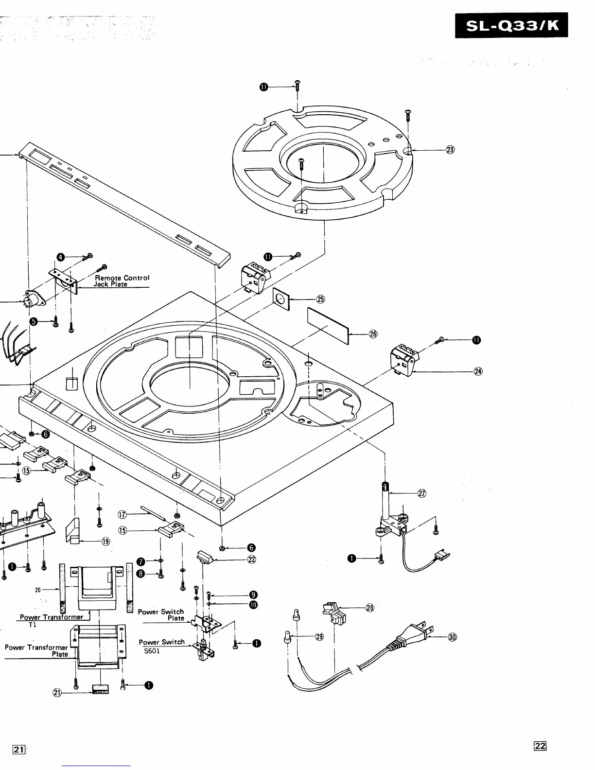
Step-by-step guide to detach the unit's bottom base assembly.
Instructions for disassembling the drive circuit PCB and stater frame coil.
Procedures for removing the tone arm drive mechanism and the tone arm itself.
How to adjust the auto-start position for accurate stylus placement on the record.
Procedures for adjusting the automatic return position for 30 cm and 17 cm records.
How to adjust the muting feature by modifying the arm lift height.