•
The
power
supply for this unit varies depending
upon
the areas. Also, the parts
used
for
power
supply are different.
So, refer to the circuit diagram and replacement
parts list.
*
[XA] area is provided
with voltage
selector and AC outlets.
*
240V
(
5
O/6
OH
2
)
for
Australia and
United
Kingdom.
*
220V
(50/60Hz) for Continental
Europe.
*
127V/1
10V/220V/240V
(50/60Hz) for
other [XA] area.
*
Phono
input
capacitance
is about
lOOpF.
^
Suggestions n
•
If noise is very
annoying while listening to an FM or AM
broadcast, switch OFF the video disc
player, compact-disc
player and turntable.
•Switch OFF
the video disc player
power
if noise is
excessive
while listening to an audio tape,
compact disc or
regular phono disc.
Notes;
•To record sounds from
a compact disc, press the input
selector
marked “CD”.
The
compact-disc-direct switch is for listening
only;
it
cannot
be used to select the compact disc
as a
recording
source.
PROTECTION
CIRCUITRY
The protection
circuitry may have operated if either of the following conditions
is noticed:
•
No
sound is
heard when the
power
is switched ON.
•
Sound stops
during
a
performance.
The function of this circuitry is to
prevent
circuitry damage if, for example, the positive
and negative speaker connection wires
are "shorted"
,
or if speaker systems
with
an
impedance
less
than the indicated
rated
impedance of
this unit are
used.
If
this occurs,
follow the procedure
outlined below:
1
.
Switch
OFF the power.
2.
Determine the
cause
of the problem and
correct
it.
3.
Switch ON the power once again'.
Note:
When the protection circuitry functions, the unit will not operate unless the power
is first switched OFF
and
then ON
again.
BEFORE
REPAIR
AND ADJUSTMENT
(1
)
Turn
off
the
power supply.
Using
a
lOfi,
5W resistor,
shortcircuit
both ends
of power
supply capacitors
(C705,
C706,
8200 iiF)
in
order to discharge the
voltage.
(2)
Before turning on
the power switch of the set .
A. Connect
the voltage controller to
the primary side.
B. Connect the
AC ampere meter to
the primary side or connect
the DC voltage metar to
the "±B"
circuit
of the
secondary side.
C. Turn
the VR of ICQ (VR401 and
VR402)
to
minimum (counterclockwise).
D. After setting the
output
to
zero of the voltage
contoller, turn on
the power switch
of the set.
And
increase
the output
of
voltage
controller
gradually.
Then, check
carefully whether the current
value of
primary side become more
than
followings value
or
whether
the DC voltage of secondary side is
increasing
slowly.
E. If
the value
of current is increasing
unusually or
the DC voltage is not
increasing,
lower the output
level
of
yoltage
contoller immediately.
F.
Check the transistors of
voltage amplifier
and current
amplifier
IC501
.
G. After repairing,
adjust the ICQ.
•
The
current
value of the
primary side at no
signal.
(Confirm the power supply
voltage
of each area
and
provided
voltage of the set.)
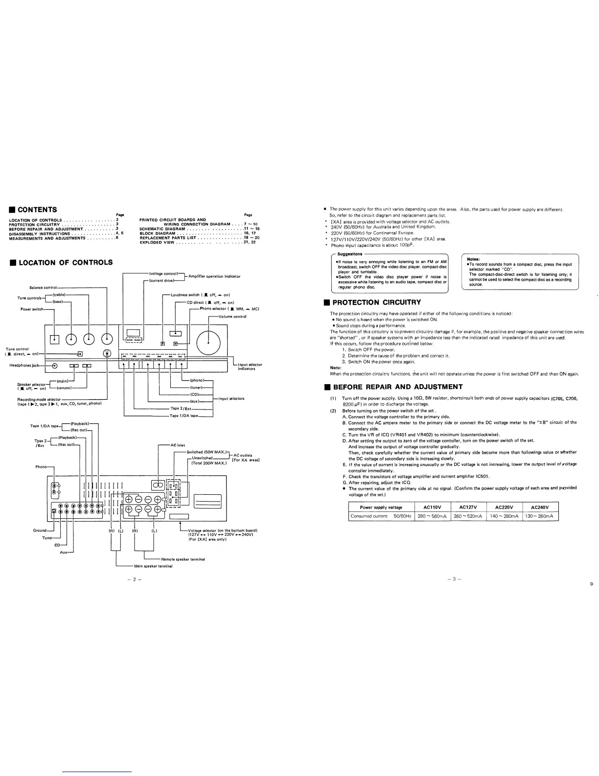
Power supply voltage
1
AC110V
AC127V
AC220V
AC240V
Consumed current 50/60Hz
280
~
560mA 260
~
520mA 140
~
280mA
130-
260mA
-
3
-
D
 Loading...