Section III – Installation
MN06135 Issue/Rev. 1.3 (6/17) 6
Note: Shields must not be terminated at the ground lugs.
h. S
ufficient slack should be provided for the wir-
ing in the AccuLoad III to permit easy removal
of the boards. With sufficient slack, the terminal
blocks can be removed and laid back out of t
he
way so that the boards can be replaced without
removing individual wires.
i. T
here is a ground lug provided in the unit. The
wire from the lug should be connected to t
he
p
roper grounding point. See Pre-Installation
Considerations, page 2.
j. T
ypical electrical installation diagrams are pro-
vided in the following sections to show the Ac-
cuLoad III and ancillary equipment. Before wir-
ing the ancillary equipment, refer to its installa-
tion manual.
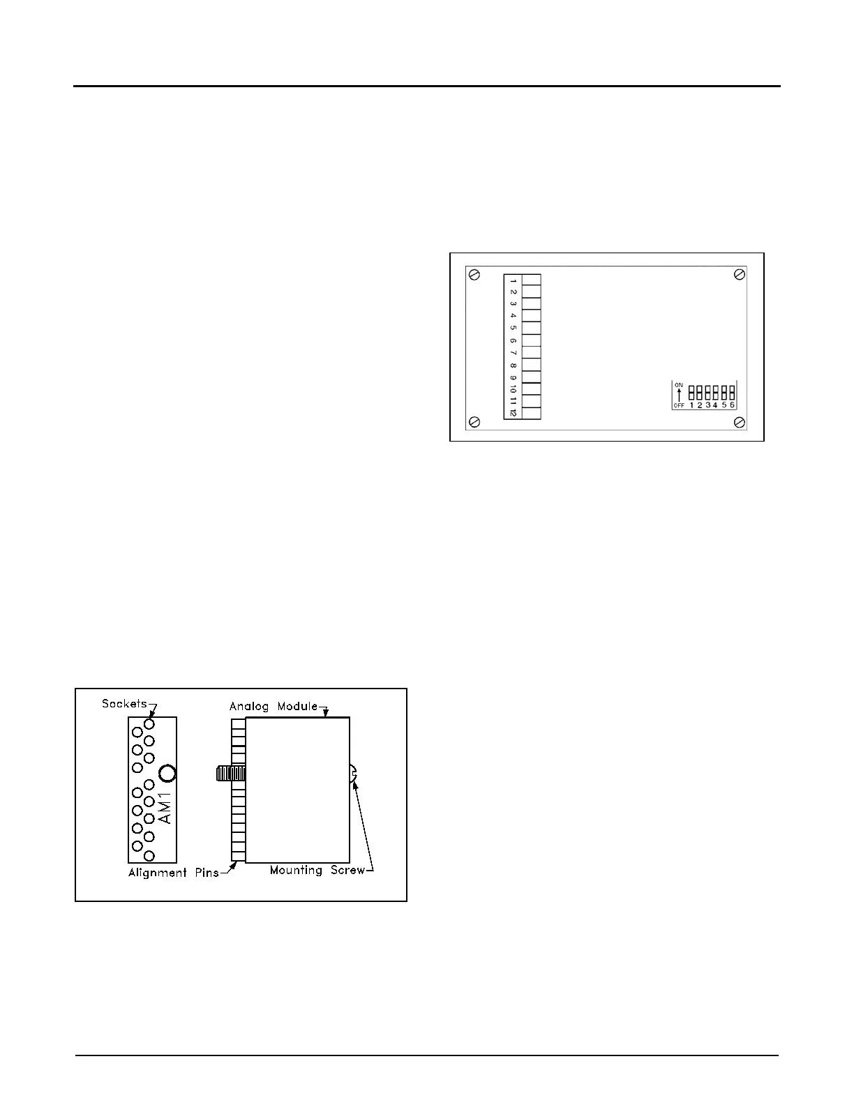
Installing and Removing the Analog I/O Module
C
aution: Turn off the power at the unit prior to installing
or removing the Analog I/O Module. Failure to do so will
damage modules.
Care should be taken when installing or removing
the Analog I/O modules so as not to damage the
board or the module. To install the module, line up
the alignment pins with the socket and push down
on the module. Once it is seated, screw in the
mounting screw until tight. Do not over-tighten the
screw. To remove the modules from the board, loos-
en the mounting screw and pull up on the module.
F
igure 1. Analog Modules
I
nput Frequency x2
If the application requires a pulse rate that is higher
than the meter is capable of putting out, the Accu-
Load III can multiply the incoming pulses times 2.
This option is activated by switches located on the
PIB boards. The PIB boards are located on the EAAI
and the BSE boards.
F
igure 2. Connector and Switches on PIB Board
The default setting from the factory is “times 1.” The
switch is closed (ON). To multiply the incoming puls-
es times 2, push the switch of the incoming pulse
channel to the open (OFF) position. The switches
are located on the PIB boards, as shown in Figure 2.
The PIB board that is located on the EAAI board is
for pulse inputs 1 through 6. The PIB board that is
located on the BSE board is for pulse inputs 7
through 12.
No
te: The switches correspond to the pulse input channels (i.e.,
Meter Pulse In #1 is equal to Switch #1.) See Table 6 for corre-
sponding Pulse Input channels.
Start-Up
When the wiring is completed and verified, power
may be applied to the unit. The displays should light,
indicating that the AccuLoad III is ready for Start-Up.
Please reference the Operator Reference Manual.