Section IV – Diagrams
MN06135 Issue/Rev. 1.3 (6/17) 21
1 Product Meters with 1 Flow Controlled Additive (AccuLoad III – Q Hardware)
Input #1 Input #2 Input #3 Input #4 Input #5 Input #6
Dual Pulse
Meter #1A Meter #1B Injector/Dens FC Inj A FC Inj 1 B Injector/Dens
Dual/Integrity
Meter #1A Meter #1B Meter #1 Bar FC Inj A FC Inj 1 B FC Inj Bar
Input #7 Input #8 Input #9 Input #10 Input #11 Input #12
Dual Pulse
Injector Injector Injector/Dens Injector/Dens Injector/Dens Injector/Dens
Dual/Integrity
Injector Injector Injector/Dens Injector/Dens Injector/Dens Injector/Dens
2 Product Meters with 1 Flow Controlled Additive (AccuLoad III – S Hardware)
Input #1 Input #2 Input #3 Input #4 Input #5 Input #6
Dual Pulse
Meter #1A Meter #1B FC Inj #1A Meter #2A Meter #2B FC Inj #1 B
Dual/Integrity
NA NA NA NA NA NA
1 Product Meter with 2 Flow Controlled Additive (AccuLoad III – S Hardware)
Input #1 Input #2 Input #3 Input #4 Input #5 Input #6
Dual Pulse
Meter #1A Meter #1B Injector/Dens. FC Inj A FC Inj 1 B Injector/Dens.
Dual/Integrity
Meter #1A Meter #1B Meter #1 Bar FC Inj A FC Inj 1 B FC Inj Bar
1 Product Meter with 1 Flow Controlled Additive (AccuLoad III – S Hardware)
Input #1 Input #2 Input #3 Input #4 Input #5 Input #6
Dual Pulse
Meter #1A Meter #1B Injector/Dens. FC Inj A FC Inj 1 B Injector/Dens.
Dual/Integrity
Meter #1A Meter #1B Meter #1 Bar FC Inj A FC Inj 1 B FC Inj Bar
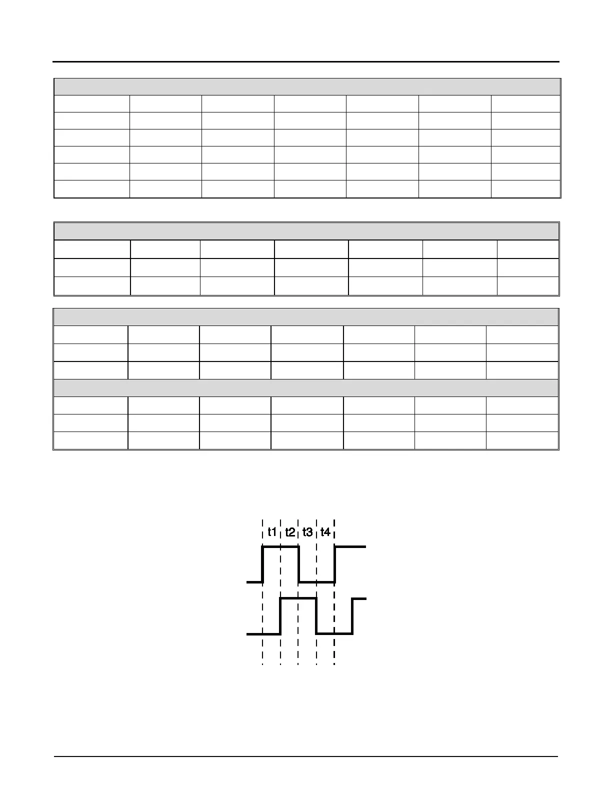
Dual Pulse Security phase shift requirements between the A and B pulses:
The AccuLoad will interpret a valid quadrature signal (90˚ phase shift between A and B pulses) if t1, t2, t3, and t4
are all greater than or equal to 25usec in the following diagram:

 Loading...


