PRIME 4 Installation and Operation Manual
Installation 5
For wiring systems using cable glands, the cable ends must be installed securely and, depending on the
type of cable, they must be adequately protected against mechanical damage.
This requirement may be ignored when a cable gland and connecting cable are used in such a way that
there is no risk of mechanical damage to the installation.
The connection cable must be of a quality that meets the thermal requirements under field service
conditions.
The equipotential/ground connection must be ensured with the installation of the sensor connected to the
complete electrical system of the installation.
Electrical ratings: 28V DC, 50 mA Max.
2.5 Wire Connections
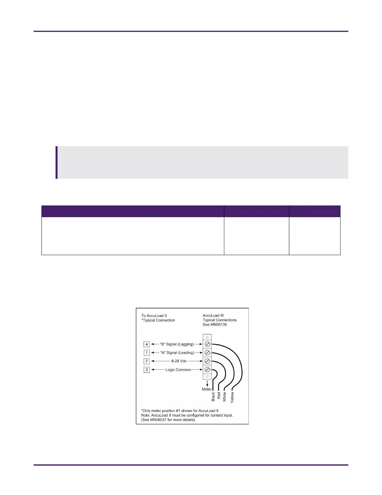
2.5.1 Quadrature (Two Channel) Installations
For quadrature (two channel) meter installations with reverse flow direction, refer to the following wiring
diagram and reverse white and yellow wire connections. Yellow wire becomes the "A" signal and white wire
becomes the "B" signal.
To avoid igniting an explosive atmosphere, do not open the enclosure unless you are sure it is not a
hazardous area. To prevent ignition of an explosive atmosphere and to avoid electric shock, disconnect
the power circuits before opening the enclosure. While the electrical circuits are energized, during oper-
ation, keep the enclosure properly closed.
Table 2: UL Brazil-Approved Installations
Marking Equipment Covered Certificate
Ex db IIC T5 …T6 Tamb = - 50 °C ≤ Tamb ≤ + 70 °C
IP65 or IP66
T
process
= -20 °C to +93 °C
T5 ≤ 93 °C / T6 ≤ 80 °C
Type SG Sensor UL-BR 19.1164X

 Loading...


