Section 2—475
OPERATING INFORMATION
Introduction
This section of the manual is intended to allow the
operator to become familiar with the instrument's power
requirements, functions of controls and connectors, and
how to obtain a few basic displays. For more complete
operating information, refer to the 475 Operators
Handbook.
Operating Voltage
This instrument is designed for operation from a
power source with its neutral at or near earth
(ground) potential with a separate safety-earth con
ductor. It is not intended for operation from two
phases of a multi-phase system, or across the legs of a
single-phase three-wire system.
This instrument can be operated from either a 115-volt
or 230-volt nominal line voltage source, 48 to 440 hertz.
The Line Voltage Selector switch in the instrument
converts the instrument from one nominal operating
voltage to the other. The Regulating Range Selector
assembly on the instrument rear panel selects one of three
regulating ranges for each nominal line voltage, and also
contains the line fuses for overload protection for both
nominal line voltages. To select the correct nominal line
voltage and regulating range, proceed as follows:
1. Disconnect the instrument from the power source.
2. To convert from 115-volts nominal to 230-volts
nominal line voltage, set the selector switch to the 230 volts
position (toward the rear of the instrument). Change the
line-cord plug to match the power source or use a
115-to-230 volt adapter.
NOTE
Color-coding of the cord conductors is as follows (in
accordance with National Electrical Code):
Line Black
Neutral White
Safety earth (ground) Green (or green with
yellow tracer)
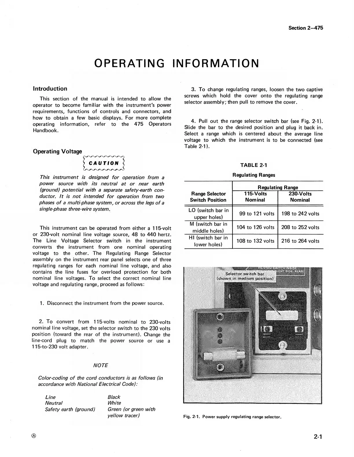
3. To change regulating ranges, loosen the two captive
screws which hold the cover onto the regulating range
selector assembly; then pull to remove the cover.
4. Pull out the range selector switch bar (see Fig. 2-1).
Slide the bar to the desired position and plug it back in.
Select a range which is centered about the average line
voltage to which the instrument is to be connected (see
Table 2-1).
TABLE 2-1
Regulating Ranges
Regulating Range
Range Selector
Switch Position
115-Volts
Nominal
230-Volts
Nominal
LO (switch bar in
upper holes)
99 to 121 volts
198 to 242 volts
M (switch bar in
middle holes)
104 to 126 volts
208 to 252 volts
HI (switch bar in
lower holes)
108 to 132 volts 216 to 264 volts
Fig. 2-1. Power supply regulating range selector.
2-1

 Loading...


