Tektronix AFG3000 Series Function Generator Guide v1.0 Portland State University
10
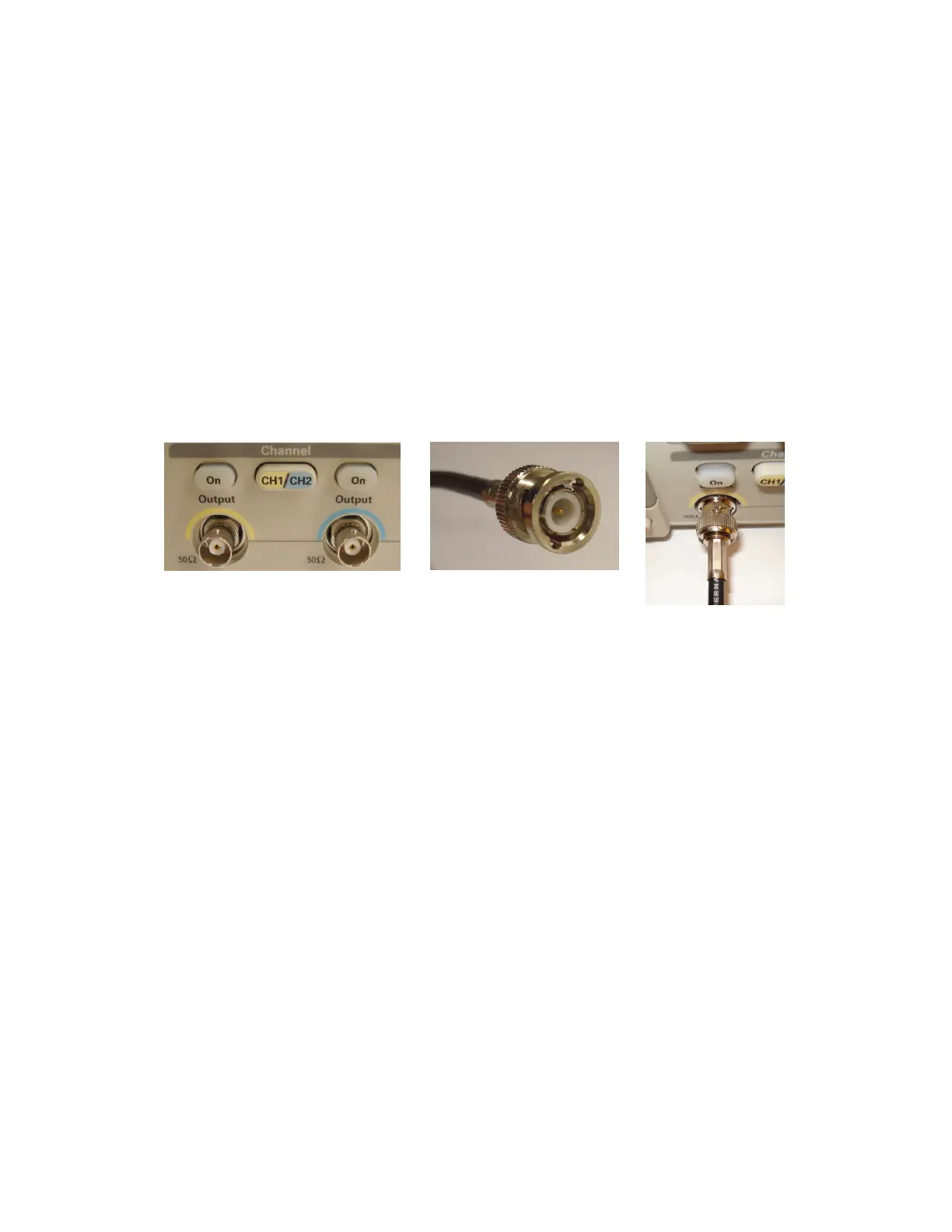
► Output Connectors
The output signals from the function generator are available at the BNC connectors on the front panel. If
a channel is currently disabled, the output signal is turned off at the corresponding BNC connector.
(Ch1 Output)
Output connector for the Channel 1 waveform signal
(Ch2 Output)
Output connector for the Channel 2 waveform signal
(Trigger Output)
This connector outputs a TTL level pulse that is synchronized with the output from
Channel 1. This can be used to trigger an attached instrument such as an
oscilloscope.
Note:
The output impedance R
O
of each channel is 50 Ω.
Figure 9: BNC connections
Female BNC (AFG3102)
Male BNC (Cable)
 Loading...


