Tektronix AFG3000 Series Function Generator Guide v1.0 Portland State University
4
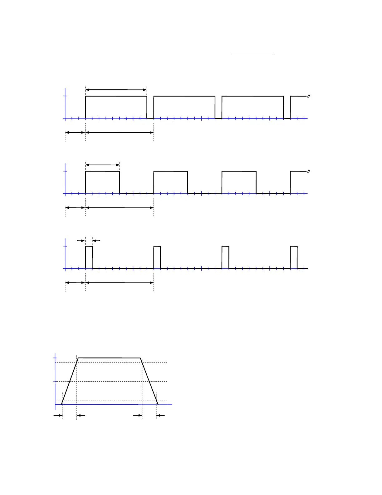
For a pulse train, the pulse duty cycle (in %) is defined as:
100⋅=
PeriodPulse
WidthPulse
Duty
Figure 4: Examples of ideal pulse trains (Ampl = 5 V, Offset = 2.5 V or High = 5V, Low = 0 V)
Depending on the situation, a pulse’s leading and trailing edge transition times may be relevant:
Figure 5: Edge transition widths for a realistic (non-ideal) pulse
Duty = 90%
V
t (ms)
Delay=
0.3 ms
Pulse Period = 1.0 ms
Pulse Freq = 1 kHz
Pulse Width = 0.9 ms
Duty = 50%
V
t (ms)
Pulse Period = 1.0 ms
Pulse Freq = 1 kHz
Pulse Width = 0.5 ms
Delay=
0.3 ms
Duty = 10%
V
t (ms)
Pulse Period = 1.0 ms
Pulse Freq = 1 kHz
Pulse Width = 0.1 ms
Delay=
t
LE
t
TE
LE
is the leading edge transition time.
t
TE
is the trailing edge transition time.
The transition times are specified using the 10%
and 90% amplitude points as references.
If t
LE
and t
TE
are a significant fraction of the total
width, then the 50% amplitude point is a better
reference for specifying the pulse width.
 Loading...


