Operation
Operation
This section
describes how to install the CT-1 or CT-2, discusses low-frequency
probing, and provides information on safety and product c are.
WARNING. To avoid e lectric shock, do not exceed the bare wire voltage ratings
(30 VAC, 42 Vpk). Depending on which instrumenttheCT-1orCT-2isconnected
to, the exposed current transformer case metal may be floating (elevated above
earth potential). W henever possible, connect the mounting stud to earth ground.
The chassis ground symbol (
) as shown on the product indicates that the
exposed current transformer case metal may not be connected to earth ground.
Use caution when the probe is not grounded.
InstallingtheCT-1orCT-2
The CT-1 or CT-2 transformers can be attached to the chassis or circuit boa rd
to measure current in transistors, diodes, or other c omponents. Any number of
transformers can be used.
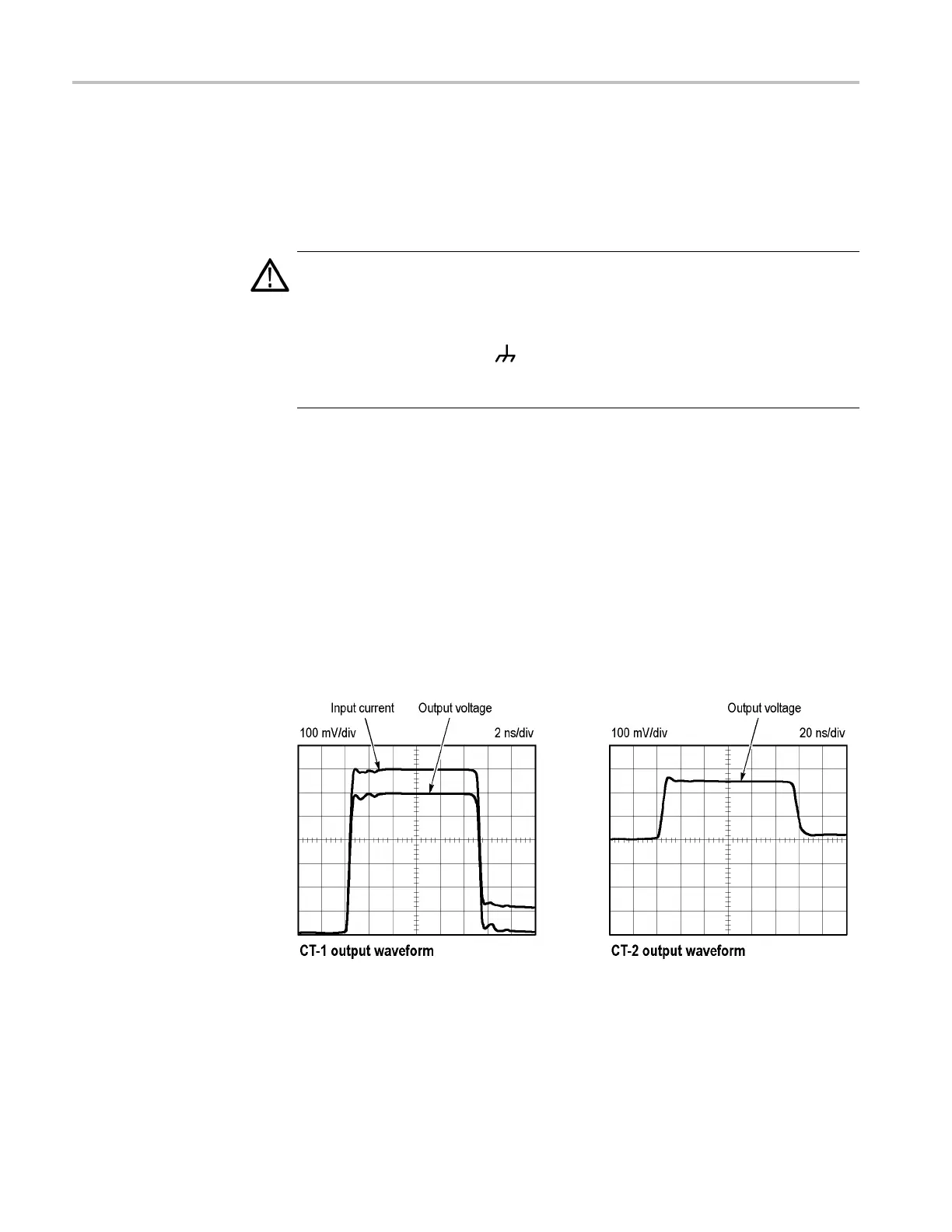
When observing the output of a CT-1 or CT-2 transformer, ensure it is terminated
into 50 Ω. If the oscilloscope input is not 50 Ω, use a suitable matching terminator
(see
recommended accessories in the Replaceable Parts List). The following
figure shows the output o f the CT-1 compared with the input pulse from a 250 ps
fast-rise pulse generator and the output of the CT-2 as seen by a 100 MHz
oscilloscope system.
Figure 5: CT-1 and CT-2 output waveforms
4 CT-1 and CT-2 Curr ent Transformer Instructions
 Loading...