Giving Demos of MSO Features
The demo procedures in the section s that follow cover key points of t he MSO Mixed Signal Oscilloscopes.
Demo XVII: Setting up Digital Channels (MSO2000, MSO3000, and MSO4000 Models)
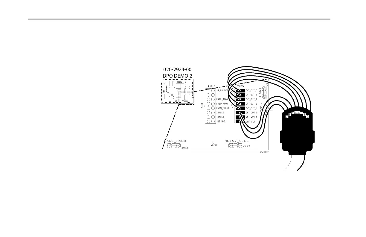
1. Connect the appropriate Digital Probe from
the oscilloscope front pa nel t o t he counter pins
on the Demo 2 board.
For the MSO4000, connect each of the probe’s
digitalgroup1channelsD0toD6toeachof
the Demo 2 board’s count signals CNT OUT
0 to CNT OUT 6. Connect the probe’s D7
channel to the board’s CNT CLK.
D7 — CNT CLK
D6 — CNT OUT 6
D5 — CNT OUT 5
D4 — CNT OUT 4
D3 — CNT OUT 3
D2 — CNT OUT 2
D1 — CNT OUT 1
D0 — CNT OUT 0
82 Demo 2 Board Instruction Manual
 Loading...