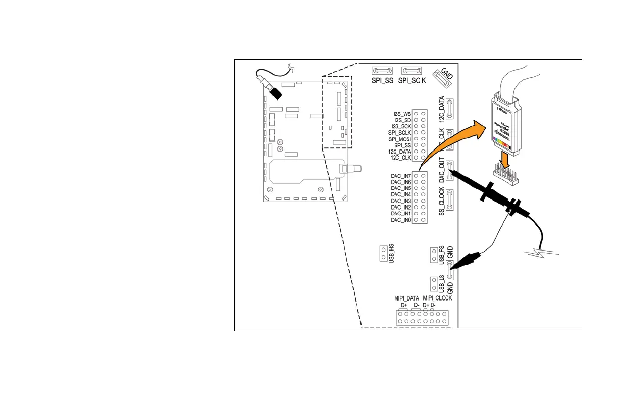
1. Connect Channel 1 to the DAC_OUT
signal on the demonstration board.
Connect the ground lead of a probe to a
point labeled GND on the demonstration
board.
2. Connect the P6316 Logic Probe to the
front-panel Logic Probe connector below
the oscilloscope display.
Note: Firmly insert the connector
into the probe port on the front of the
oscilloscope until you hear an audible
‘click’. Test that you cannot remove the
probe without pressing the buttons on
the sides of the connector.
3. Connect Group 1 of P6316 digital probe
to J1002 header labeled DAC_IN_0
through DAC_IN_7 on the demonstration
board.
Note: Make sure to connect the signal
side of the probe header, with the color-
coded channel labels, to the signal side
of the connector and the ground side
of the probe to the ground side of the
connector.
Figure 22.
www.tektronix.com/mdo3000 31
MDO3000 Series Oscilloscope
Demonstration Guide

 Loading...


