DAC Input, Parallel
Board label: DAC_IN0, DAC_IN1, DAC_IN2, DAC_IN3, DAC_IN4,
DAC_IN5, DAC_IN6, DAC_IN7
Grid location: H3, H4
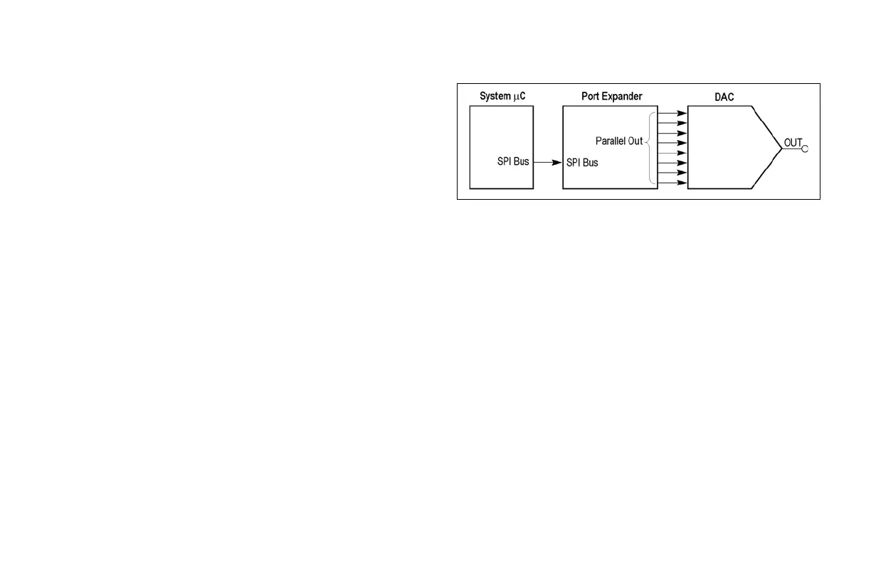
Description: These signals are the input to the DAC. These are also
the 8-bit parallel output signals of the port expander in the middle
of the mixed signal chain. The sine wave data from the SPI bus is
converted to 8 parallel bits to drive the DAC. DAC_IN0 is the LSB.
(See Figure 35.)
DAC Output
Board label: DAC_OUT
Grid location: H3
Description: This is the output of the DAC at the end of the mixed
signal chain. The DAC is driven from the port expander. The DAC
output is a sine wave. Since the output is not filtered, the digitizing
levels are present in the output waveform. (See Figure 35.)
The resulting DAC voltage is a sine wave with an amplitude of 0 to 3
volts, and a period of 31 ms.
Figure 35. Mixed signal chain block diagram.
www.tektronix.com/mdo3000 47
MDO3000 Series Oscilloscope
Demonstration Guide

 Loading...


