Performance Verification
Check Input Impedance
(Resistance)
This test check
s the Input Impedance.
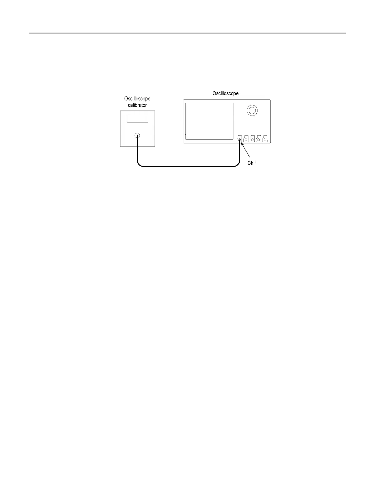
1. Connect the output of the oscilloscope calibrator (for example, Fluke 9500) to
the oscillosc
ope channel 1 input, as shown below.
2. Push the front-panel Default Setup button to set the instrument to the factory
default settings.
3. Push the front-panel channel button for the oscilloscope channel that you are
testing, as shown in the test record (for example, 1,2,3,4).
4. Confirm that the oscilloscope and calibrator impedances are both set to
1MΩ.The default Impedance setting is 1 MΩ.
5. Turn the Vertical Scale knob to set the vertical scale, as shown in the test
record (for example, 10 mV/div, 100 mV/div, 1 V/div).
6. Measure the input resistance of the oscilloscope with the calibrator. Record
this value in the test record.
7. Repeat steps 5 and 6 for each volt/division setting in the test record.
8. Change the oscilloscope and calibrator impedance to 50 Ω and repeat steps 5
through 7.
9. Repeat steps 4 through 8 for each channel listed in the test record and relevant
to the model of oscilloscope that you are testing, as shown in the test record
(forexample,2,3,or4).
36 MSO4000 and DPO4000 Series Specifications and Performance Verification
 Loading...


