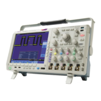
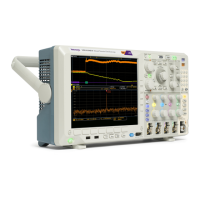
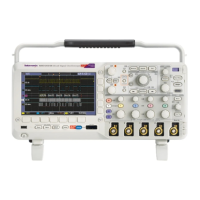
Replaceable Parts List
Table 5: Replac
eable parts – Display, Analog board, and Main board
Figure
and
index
no.
Tektronix
part n o.
Serial
no.
effective
Serial
no.
discont’d Qty. Name and description
9-
DISPLAY, ANALOG BOARD & MAIN BOARD
-1 850-0110-00 1
FRAME ASSEMBLY, DISPLAY: LCD
SCREW, MACHINE: 6–32 x 0.250, PNH, STL, ZNPL, T-15 TORX DRIVE
------DISTRIBUTIONOFTHE211-1272-00SCREWS-------
6 screws attach the LCD assembly to the front chassis.
15 screws attach the Main board assembly to the front chassis.
6 screws attach the Analog board assembly to the front chassis.
12 screws attach the rear chassis to the front chassis: 4 across the top flange of the rear
chassis,2oneachsideflange, and 4 across the bottom flange of the front chassis.
-2 211-1272-00 40
1 screw attaches the ground jack to the front chassis.
-3 441-2608-00 1
CHASSIS ASSEMBLY, FRONT
-4 211-1273-00 8
SCREW, PT, K35–1.57, PAN HEAD, STL, ZNPL, T-15 TORX DRIVE
-5
131-6643-00 6
CONTACT, ELEC: GROUNDING, 0.169 L X 0.250 W X 0.320 D, ELECTROLESS
NICKEL PLATE
-6 131-6417-00 4
CONTACT, ELEC: GROUNDING, 0.600 L X 0.250 W X 0.220 D, ELECTROLESS NICKEL
PLATE
-7
131-7622-00 1
CONN, RECEPT; GROUND JACK
-8
-------
1
MAIN BOARD ASSEMBLY. Return the instrument to Tektronix for service. Must be
replaced with the ANALOG BOARD ASSEMBLY.
-9
-------
1
ANALOG BOARD ASSEMBLY. Return the instrument to Tektronix for service. Must be
replaced with the M AIN BOARD ASSEMBLY.
-10 351-1134-00 1
DIGITAL PROBE GUIDE (MSO models only)
-11 129-1693-00 1
SPACER, POST
MSO4000B and DPO4000B Series Digital Phosphor Oscilloscopes Service Manual 35

 Loading...


