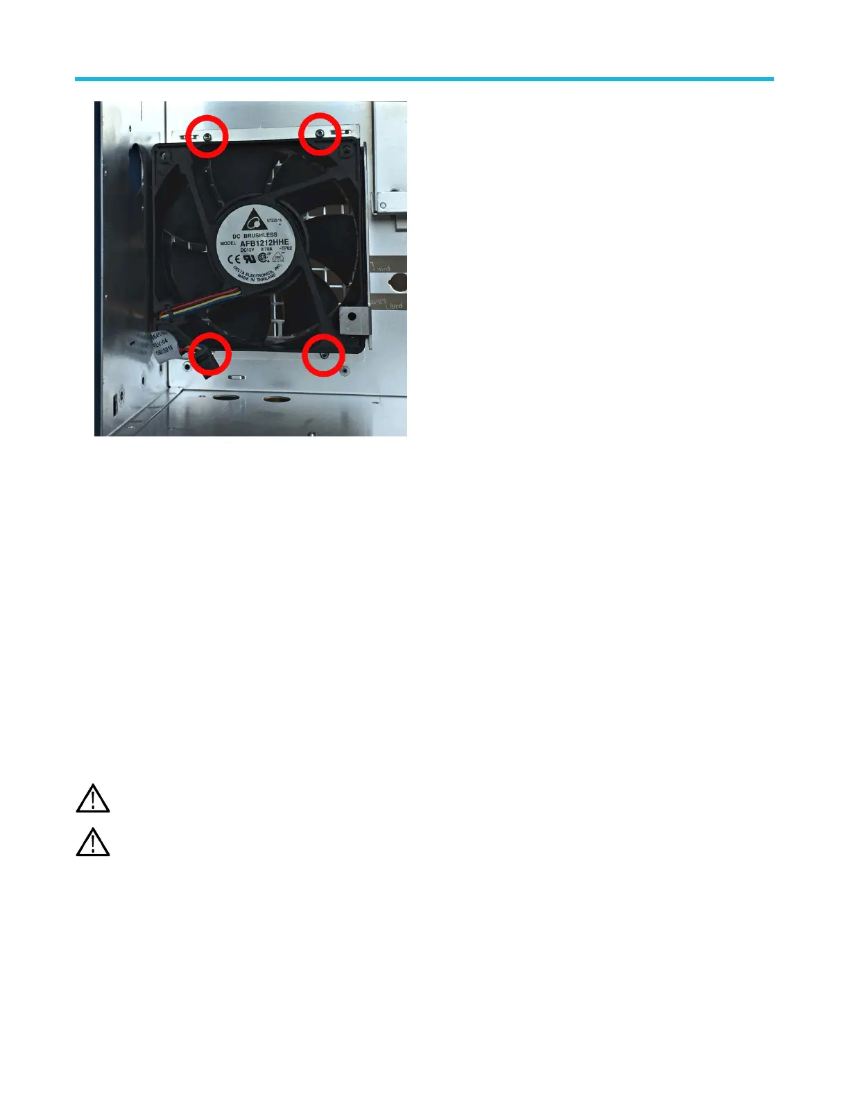
2. Remove the main fan assembly from the rear chassis.
3. T
o remove the fan from the bracket, carefully pull the fan from each corner of the bracket to disconnect the elastic fan attachments.
4. To reinstall, reverse the steps. Install the fan on the bracket in the correct orientation for the fan power cable (see photo). Use a needle
nose plier to reinstall the fan elastic attachments on each corner. Tighten the T-10 Torx screws to 0.65 N·m when reinstalling.
Remove M.2 memory board
Use this procedure to remove the M.2 memory board from the carrier interface assembly to sanitize the instrument before sending for
repairs at a Tektronix Service Center.
Before you begin
• To prevent electrostatic damage to components whenever you work on the instrument, wear properly-grounded electrostatic prevention
wrist and foot straps, and work in a tested antistatic environment on an antistatic mat.
• Remove carrier interface assembly on page 24
• Remove the AFG riser assembly on page 26
About this task
Removing the M.2 memory board sanitizes the instrument, ensuring that user settings and acquisition data are no longer on the
instrument. Removing the M.2 board also removes the instrument calibration constants and any option licenses that you have installed.
Note: The M.2 memory board is only in instruments with a serial number below B020000 or below C040000.
Note: If the M.2 board is removed before sending the instrument to T
ektronix for repair, Tektronix will install a new M.2 board and
you will be charged for the new board.
You will need to reassemble the instrument and send it to your nearest Tektronix Service Center to have a new M.2 board installed and the
instrument recalibrated.
After the instrument is returned, you will need to reinstall any option licenses.
Procedure
1. Remove the seven
T-10 Torx screws from the carrier board (marked in red). Remove the five T-8 Torx screws from the carrier board
heat sink (marked in yellow).
Maintenance
5 Series MSO Service Manual MSO54, MSO56, MSO58 28
 Loading...


