15
2. In the default trigger setting, the oscilloscope looks for a rising edge on the channel 1 input signal.
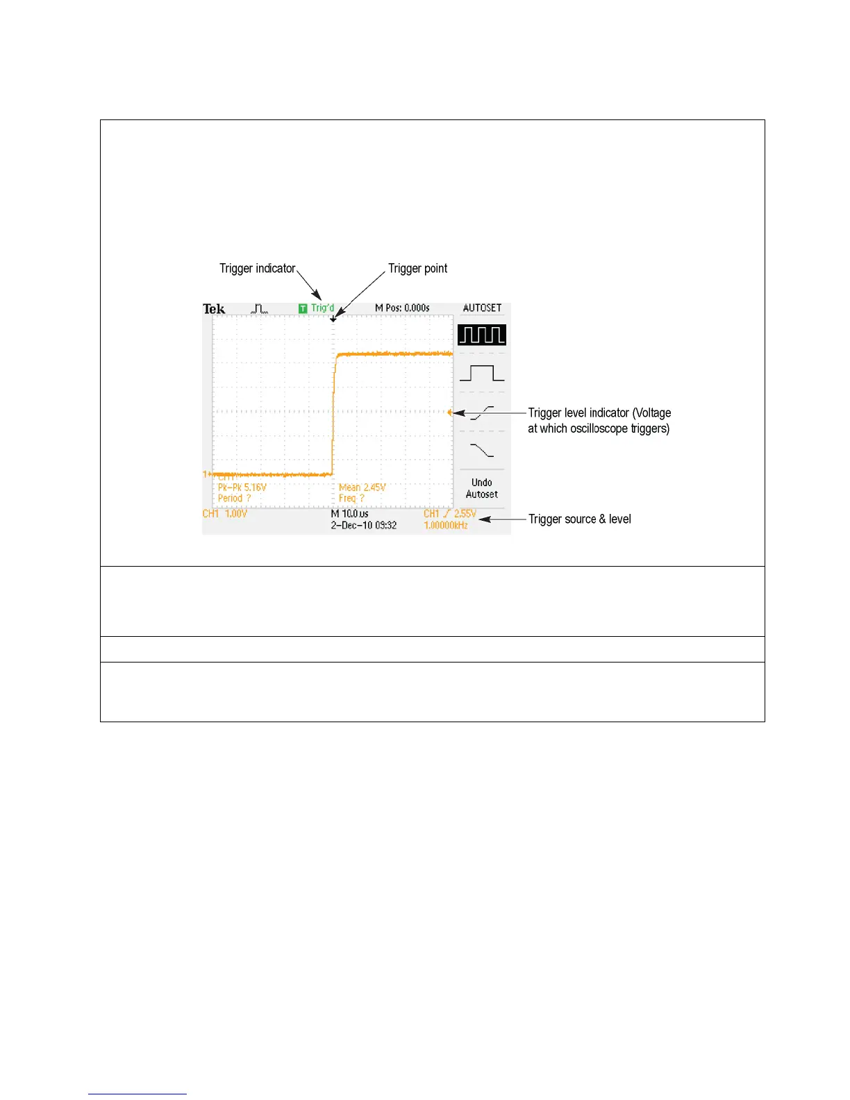
The trigger level control is used to set the voltage at which the oscilloscope triggers. The waveform is
displayed with the rising edge aligned with the trigger point (indicated by the white down arrow icon at
the top of the display). The trigger voltage level is shown by a yellow arrow on the right side of the
display.
Explanation of trigger indicators on oscilloscope display:
a. Turn the Trigger Level knob until the trigger level, as indicated by the yellow arrow on the right
side of the screen, is above the top of the waveform (about 5.5 V) resulting in an
un-triggered display.
Key Points to Remember
1. A trigger defines when a signal is acquired and stored in memory.
2. The trigger level must be within the signal range to properly trigger the oscilloscope.
3. For a repetitive signal, a trigger is necessary to obtain a stable display.

 Loading...


