5
Initial Setup and Screen Explanation
Creating a Stable Display
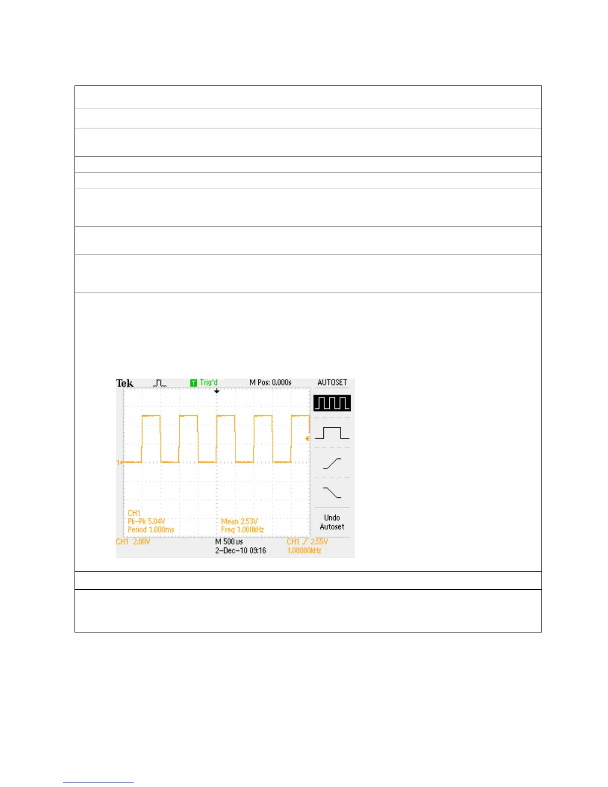
1. The following steps will describe how to automatically create a stable oscilloscope display using a
1 kHz, 5 V
pk-pk
square wave.
a. Power up the oscilloscope by pushing the power button.
b. Push the front-panel Default Setup button to set the oscilloscope to a known starting point.
c. Connect a passive probe to the channel 1 input. To connect a probe that uses a BNC
connector, push and turn the probe connector until it slides on the oscilloscope channel input
connector. Then, turn the probe locking ring clockwise to lock the probe connector in place.
d. Attach the probe’s alligator style ground lead to the ground connector next to the oscilloscope
display.
e. Attach the probe tip to the Probe Comp connector just above the ground lead connector. This
connector provides a 1 kHz square wave that this lab will use to demonstrate the operation of
an oscilloscope.
f. Push the front-panel AutoSet button to cause the oscilloscope to automatically set the vertical,
horizontal and trigger settings for a stable display of the probe compensation 1 kHz square
wave.
PLEASE NOTE: All screenshots in this Guide were taken in ink-saver mode to allow for
better visibility of signal changes in a printed document.
Key Points to Remember
1. To return the oscilloscope to a known state, push the Default Setup button.
2. The AutoSet button adjusts the vertical, horizontal and trigger settings such that four or five cycles
of the waveform are displayed with the trigger near the middle of the screen
.

 Loading...


