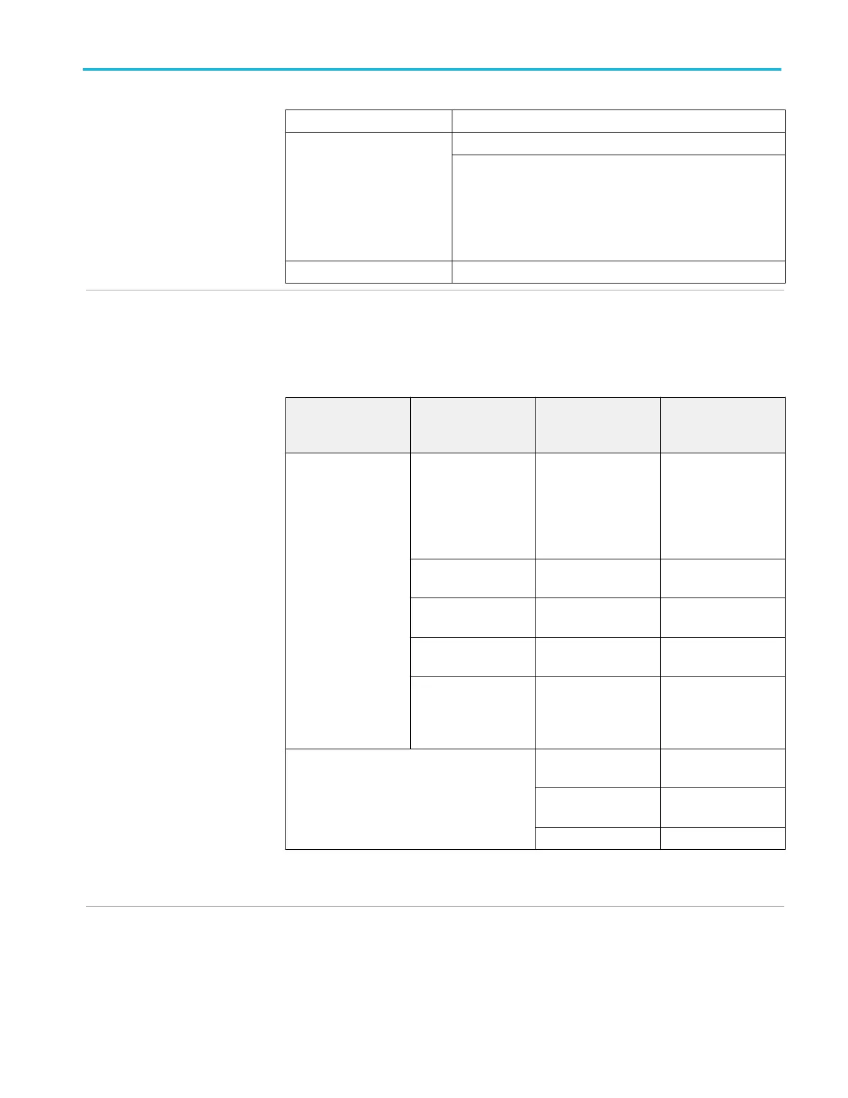
Edge trigger
Trigger modes Auto, Normal, Single sequence
Trigger coupling (analog
channels)
AC, DC, Noise Reject, High Freq Reject, Low Freq Reject
The Aun In path does not have a DC blocking capacitor ahead of
the trigger input circuit. The roll off associated with AC coupling
happens after the input circuit. When attempting to trigger on an
AC signal that has a DC offset, use care to avoid overloading the
input of the Aux In circuit. For signals that have a large DC offset,
using Channel 1 or Channel 2 with AC coupling is preferred.
Trigger slope Rising edge, Falling edge
√ Sensitivity, Edge-Type trigger,
DC coupled
Measurement Style A: The minimum signal levels for achieving stable frequency indication on the
Trigger Frequency Counter within 1% of correct indication.
Measurement Style B: Section 4 10.2 in IEEE Std. #1057. The minimum signal levels required for
stable edge triggering of an acquisition when the trigger Source is DC coupled.
Trigger source Sensitivity
(Measurement style
A), typical
Sensitivity
(Measurement style
B)
Channel inputs All products 0.4 division from DC to
50 MHz
0.6 divisions >50 MHz
to 100 MHz
0.8 divisions >100 MHz
to 200 MHz
0.8 div from DC to
10 MHz > 2 mV/div)
2.5 div from DC to
10 MHz (2 mV/Div)
TBS1072C 3 div between 10 MHz
and 70 MHz
1.5 div between
10 MHz and 70 MHz
TBS1102C 3 div between 10 MHz
and 100 MHz
1.5 div between
10 MHz and 100 MHz
TBS1052C 3 div between 10 MHz
and 50 MHz
1.5 div between
10 MHz and 50 MHz
TBS1202C 3 div between 10 MHz
and 200 MHz
1.5 div from 10 MHz
and 100 MHz
2.0 div above 100 MHz
to 200 MHz
Aux In 300 mV from DC to
100 MHz
200 mV from DC to
100 MHz
500 mV from 100 MHz
to 200 MHz
350 mV from 100 MHz
to 200 MHz
TBS1202C TBS1202C
Trigger frequency feadout typically stabilizes at 50% more signal than generates a stable visual
display.
Triggering system (cont.) Specifications
TBS1000C Series Specification and Performance Verification 7
 Loading...


