Performance Tests
1–86
TDS Family Performance Verification and Specifications
Equipment
Required
Sine wave generator (Item 19)
Level meter and power sensor (Item 20)
Two male N to female BNC adapters (Item 23)
Two precision coaxial cables (Item 5)
Prerequisites See page 1–15
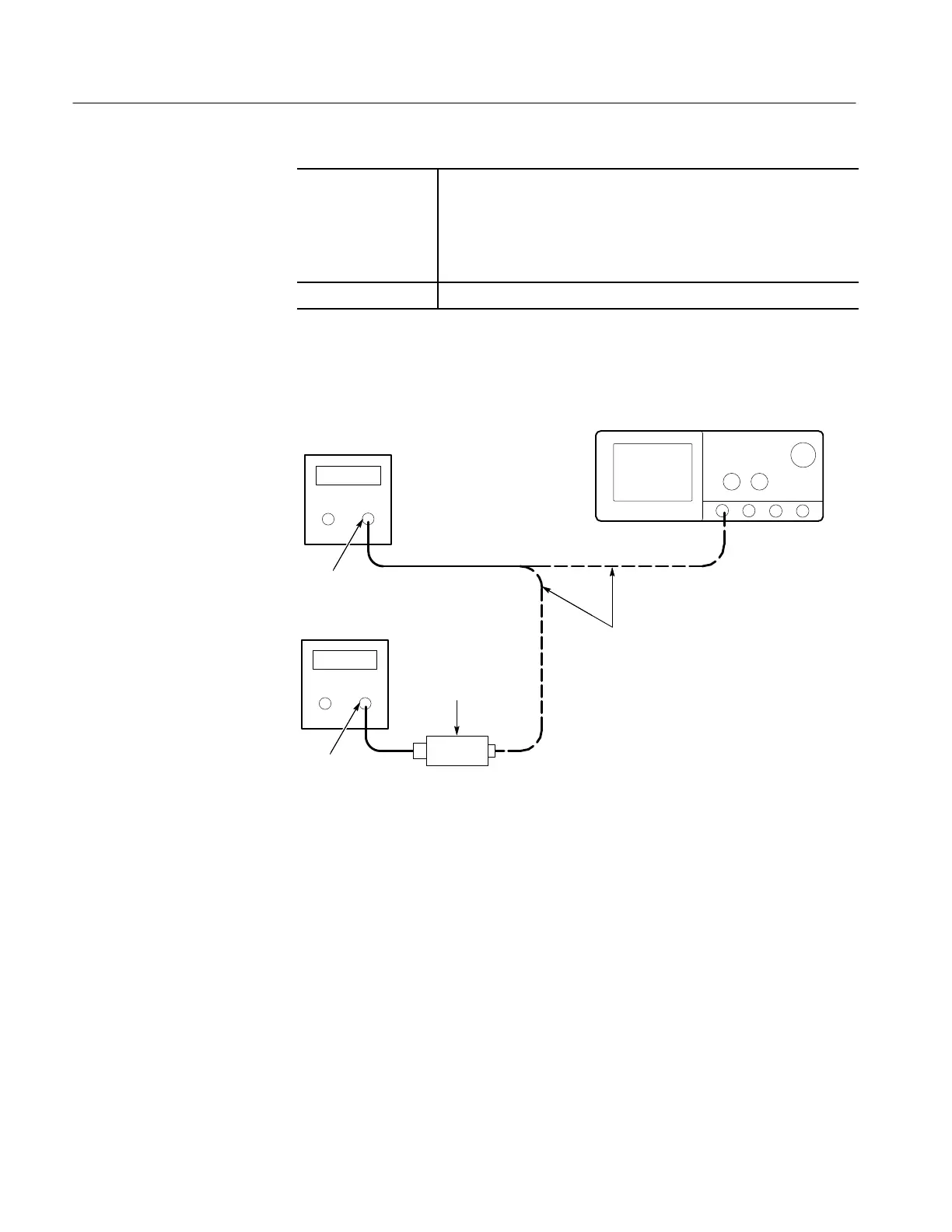
1. Install the test hookup: Connect the equipment as shown in Figure 1–42
(start with the sine wave generator connected to the digitizing oscilloscope).
Digitizing Oscilloscope
Level
Meter
Power
Sensor
Sine Wave
Generator
Output
Input
Connect the sine wave
generator to the
oscilloscope and the
power sensor as
directed in the text.
Figure 1–42: Equipment Setup for Maximum Amplitude
2. Set the Generator:
H Set the sine wave generator to a reference frequency of 10 MHz.
H Adjust the sine wave generator amplitude to the required number of
divisions as measured by the digitizing oscilloscope.
3. Record the reference level:
H Disconnect the sine wave generator from the digitizing oscilloscope.
H Connect the sine wave generator to the power sensor.
H Note the level meter reading.
 Loading...


