Performance Tests
TDS Family Performance Verification and Specifications
1–81
c. Check Sync Duty Cycle.
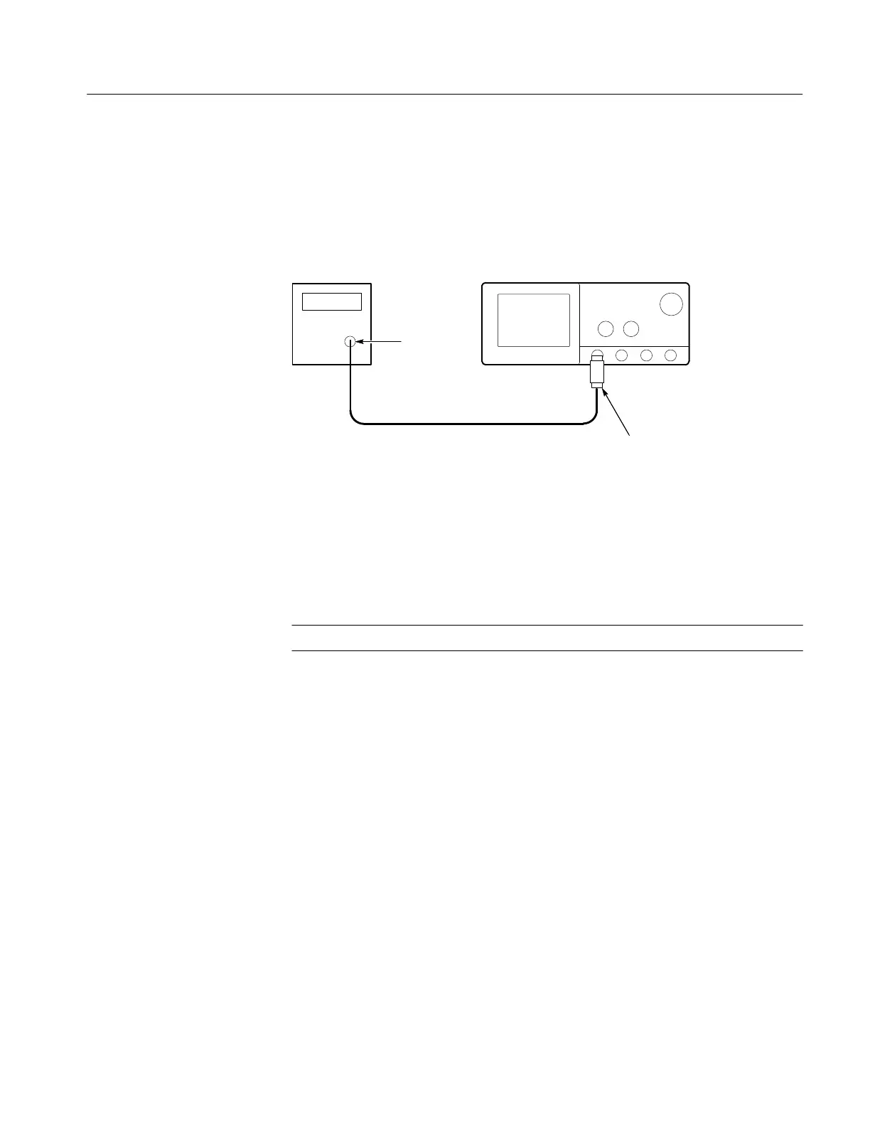
H Connect the pulse generator through a 50 W cable and a 50 W
terminator to the oscilloscope CH1 input. See Figure 1–38.
Pulse
Generator
Digitizing Oscilloscope
50 Cable
50
Terminator
Output
Figure 1–38: Setup for Sync Duty Cycle Test
H Turn the pulse generator OUTPUT (VOLTS) control until the signal
on the oscilloscope shows a one division negative going pulse. See
Figure 1–39.
NOTE. You may need to adjust the trigger level control to obtain a stable trigger.
 Loading...


