University of Portland - p. 2 of 9 - Oscilloscope - TDS3012B.docx
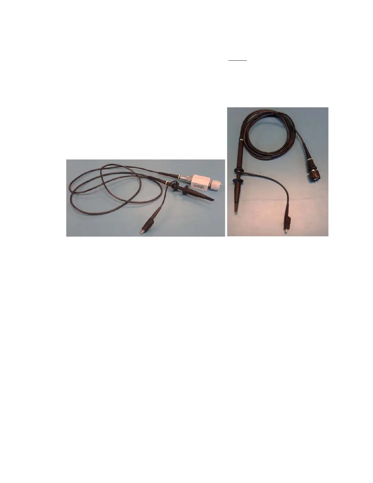
3. Connect a 10X high-impedance probe (see Figure 2) to the channel 1 BNC connector
which is labeled as CH 1. When connecting the probe, gently push the connector while
rotating it clockwise until it slides in, then turn it clockwise so that it snaps securely in
place. The 10X high-impedance probe should ONLY be connected to the oscilloscope,
not to any other equipment. (To remove the probe, turn it counter-clockwise to release,
then gently pull on the connector. Please do NOT pull on the cable.)
Figure 2: 10X High-Impedance Scope Probes (Two Different Models)
4. The alligator clip on the probe is the ground lead. In order to make sure that the probe is
working correctly, connect the ground lead to the lower connector of the Probe Comp
port as shown above in Figure 1.
5. If you gently push on the probe tip, a hook is exposed that can be connected to a wire.
Connect the probe tip to the upper Probe Comp terminal (see Figure 1). The Probe Comp
port generates square wave that oscillates between 0 and 5V.
6. Press the Autoset button, which selects certain settings automatically depending on the
input signal. The display should look similar to that in Figure 1.
7. Check that the oscilloscope is reading the Probe Comp port voltage correctly (see below
for details on how to read the voltage). If the voltage isn’t reading correctly, refer to the
section Probe Setup below.
8. Connect the probe tip to the voltage in the circuit that you want to measure. Connect the
alligator clip to the circuit ground.
Note that the ground lead of the oscilloscope is connected to earth ground internally by
the oscilloscope, so it should only be connected to ground in a circuit. If the ground lead
is connected anywhere else in a circuit, it will short that node to earth ground.
 Loading...