A:SW1 s,VRODWHG
Emulation and UART
Communication
Enable Switch
A:J1 s86%
Emulation/UART
Connector
J8 s86%+RVW/
Device Connector
U5 sX6'&DUG
Connector Slot
SW1 s%RRW0RGH
Switch
SW3 s$'&95()+,
Control Switch for
ADC (C and D)
SW2 s$'&95()+,
Control Switch for
ADC (A and B)
U1 s&2000 Delfino
F28379D
Microcontroller
J2-J7 s86%3+<
Connection Enable
Jumpers
www.ti.com
Hardware References
9
SPRUI76A–March 2017–Revised January 2019
Submit Documentation Feedback
Copyright © 2017–2019, Texas Instruments Incorporated
Delfino™ TMS320F28379D controlCARD R1.3
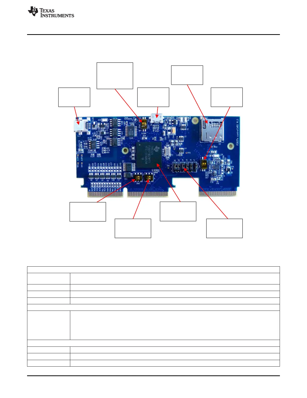
5 Hardware References
Table 2 shows the various connections available on the board. Figure 6 illustrates the location of many of
these components on the board.
Figure 6. Key components on the controlCARD
Table 2. Hardware References
Connectors
A:J1 Emulation/UART connector - USB mini A connector used to provide xds100v2 emulation and USB-to-UART(SCI)
communication through FTDI logic. A:SW1 determines which connections are enabled to the MCU.
U5 SD Micro card slot – connects to MCU via SPI
J8 USB connector – USB micro AB connector supports USB 2.0 host/device
J9 Enables a secondary board to have access to the F28379D’s EMIF2 and several other digital signals.
Jumpers
J2-J7 USB PHY connection enable/disable jumpers:
• All jumpers up – The MCU will be connected to the USB PHY on the controlCARD via GPIOs 42, 43, 46, 47,
120, and 121
• .All jumpers down – The MCU will not connect to the USB PHY and all signals will instead go through the 180-
pin controlCARD connector.
LEDs
LD1 Turns on when the controlCARD is powered ON (green)
LD2 Controlled by GPIO-31 with negative logic (red)
LD3 Controlled by GPIO-34 with negative logic (red)

 Loading...


