INS881EN-2 32/55
1.6 Testing, commissioning and LED indications
Following initial power the device will take 180s to calibrate the anti-
masking function. There should be no obstructions or movement in the
field of view of the device whilst this calibration takes place.
When installation is complete, the device should be thoroughly walk tested to
ensure the desired volumetric protection is being achieved, and any adjustments
to the device are made to cater for the specific location and any local site
conditions.
Note: If you need to make adjustments to any of the mode switches or the
microwave range you will need to again power up the device for 180s with no
activity in the protected area to allow the anti-masking to calibrate correctly.
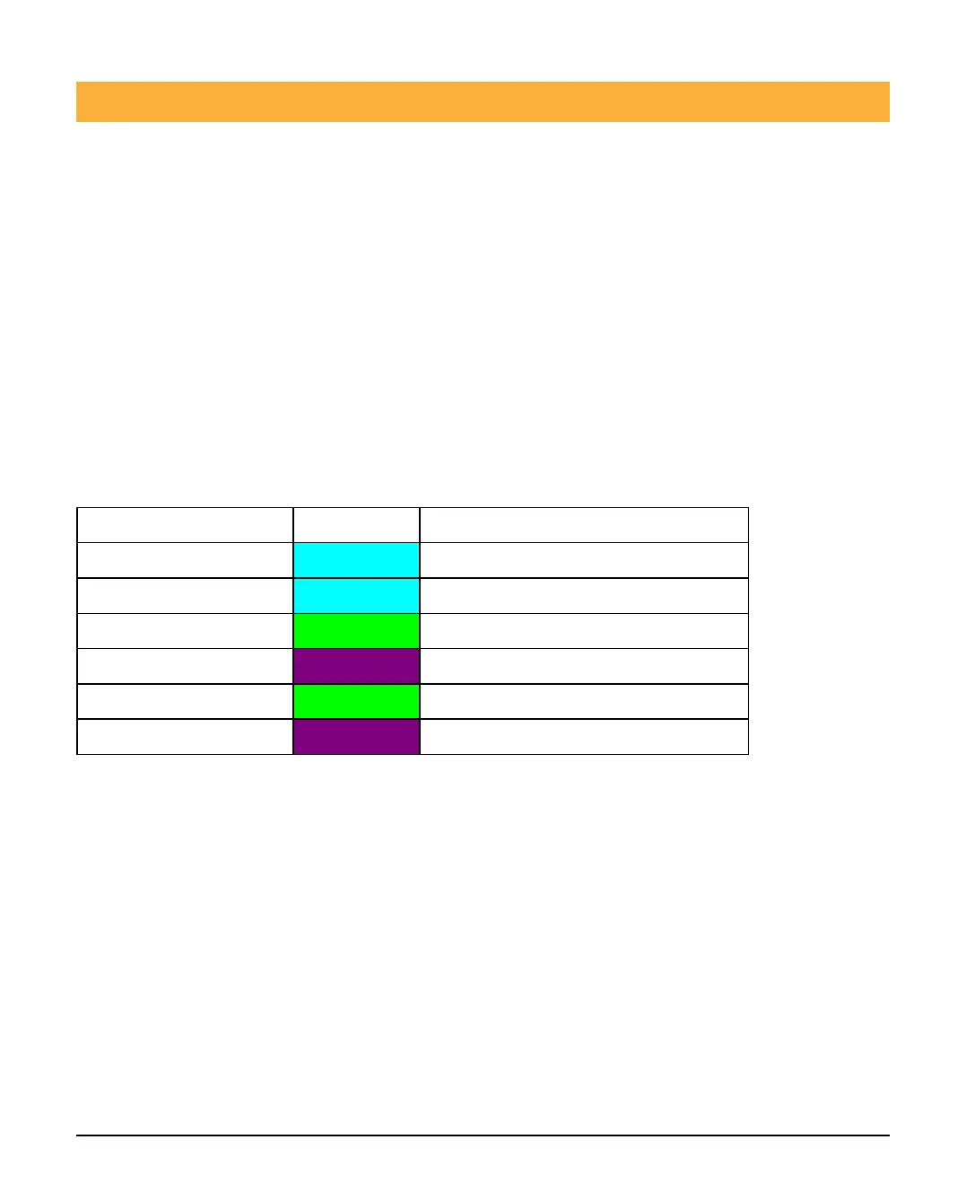
Note: LED’s are disabled during normal use if the RLED switch is ON.
State Colour Flash
Warm up
Flash 0.5s on 0.5s off
Alarm
PIR only
MW only
Mask
Flashing
Fault
Flashing
Walk test
Walk test all devices to ensure you have adequate coverage, and that there are no
obstructions in the detection area.
Microwave Range Adjustment
Devices are supplied with the microwave adjustment potentiometer set at the mid-
point.
The microwave should be adjusted according the area to be protected, and great
care should be taken to ensure the microwave cannot “see” beyond protected
area. LED indication of the microwave pickup allows for accurate setting of the
 Loading...