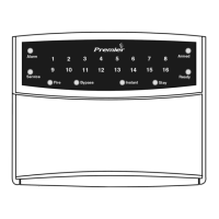
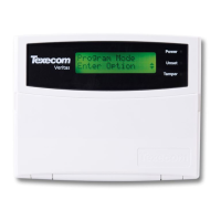
The Premier keypad is only compatible with Texecom Premier control panels. Any
combination of Premier Elite keypads can be used. Keypads can be connected serially
(daisy chain), in parallel (star) or any combination of the two.
1. Installation
It is strongly recommended that the system is completely powered down (mains and
battery) before wiring a keypad. Connect the keypad to the control panel using 4-core
cable as follows:
Wiring
4 INS524-3
GB
Keypad Control Panel Description
+ + +12V Supply
- - 0V Supply
T T Transmit Data
R R Receive Data
The networks are made up of four terminals incorporating power and data. To
ensure correct operation, all four terminals on the device must be connected to the
corresponding terminals on the control panel or previous device.
Keypads can be connected using 4-core cable. However, it is recommended that 6
or 8-core cable is used as the spare cores can be used to ‘Double Up’ on the power
connections if needed.
• Standard 7/0.2 alarm cable can be used for most installations. However, under
certain conditions it may be necessary to use screened cable.
• Please refer to the Control panel Installation Manual for details on wiring,
programming and testing the zones, outputs and loudspeakers.
Address DIL 1 DIL 2 DIL 3 DIL 4
1
On or Off
Off Off Off
2 Off
On
Off Off
3 Off Off
On
Off
4 Off Off Off
On
5
On
Off Off
On
6 Off
On
Off
On
7 Off Off
On On
8
On
Off
On On
Engineers
On On On On
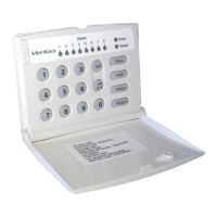
Selecting an Address
Each keypad must be assigned a different address using the DIL switches located on
the left hand side of the PCB. The table below shows the keypad addressing:
Never set two keypads on the same network to the same address.
Keypads are factory set to address 1.
INS524-3 5
Operating Voltage
10 - 13.9V
DC
Current Consumption LCD: 10mA-170mA LCDL: 20mA-200mA
Network
4-wire standard 7/0.2 alarm cable up to 250m.
Star, Daisy Chain or any combination.
Zones
2
Output
100mA switched to 0V
Back Lighting
Fully Adjustable
Speaker Output
Minimum Load 8 Ω (programmable volume)
Maximum Current 325mA
Operating Temperature
-10°C (+14°F) to +50°C (+122°F)
Storage Temperature
-20°C (-4°F) to +60°C (+140°F)
Maximum Humidity
95% non-condensing
EMC Environment
Residential, Commercial, Light Industrial or Industrial
Electrical
Standards
Warranty
Conforms to European Union (EU) Electro-Magnetic Compatibility (EMC) Directive
89/336/EEC (amended by 92/31/EEC and 93/68/EEC).
The CE mark indicates that this product complies with the European requirements for
safety, health, environmental and customer protection.
This product is a Type A Non moveable device and is suitable for use in systems
designed to comply with EN50131-1 & EN50131-3 at Grade 2 & 3 Class II.
All Texecom products are designed for reliable, trouble-free operation. Quality is carefully
monitored by extensive computerised testing. As a result the Premier Elite keypads are
covered by a two-year warranty against defects in material or workmanship.
As the Premier Elite keypads are not a complete alarm system but only a part thereof,
Texecom cannot accept responsibility or liability for any damages whatsoever based
on a claim that the Premier Elite keypad failed to function correctly. Due to our policy
of continuous improvement Texecom reserve the right to change specification without
prior notice.
Premier is a trademark of Texecom Ltd.
2. Specifications
GB
 Loading...