Simple to View:
Cause of Alarm
1. Return to the Standard Display
Screen.
2. Press the MENU Key.
3. Press the UP or DOWN Key until
the Alarm Menu appears.
4. Press the SELECT Key.
The Alarm Display will appear.
5. If alarms are present, the quantity
of alarms and the most recent alarm
code number will be shown.
6. If necessary to view all alarms,
scroll down using the DOWN Key.
7. If a serious condition occurs, the
unit will be shut down to prevent
damage to the unit or the load. If
this occurs, the Alarm Icon will
appear, the display and backlight
will flash on and off.
NOTE: For more detailed infor-
mation, see the Operation chapter in the appropriate unit operating
manual.
Simple to View:
Clearing Alarm Codes
1.If the alarm situation has been
resolved press the CLEAR Key to
clear the alarm.
2. The display will briefly show
CLEARING ALARMS – PLEASE
WAIT. Then the Alarm Menu will
reappear.
3. Press the HELP Key for
additional information regarding the
alarm shown on the display. Also
see the complete Alarm Code list in
the next column.
4. To return to the Main Menu press
the EXIT Key. To return to the
Standard Display press the EXIT
Key again.
NOTE: For more detailed information, see the Operation chapter in the
appropriate unit operating manual.
Simple to
Determine:
Cause of Alarm
0No Alarms Exist
2 Evaporator Coil Sensor
3 Control Return Air Sensor
4 Control Discharge Air Sensor
5 Ambient Air Sensor
6 Coolant Temp Sensor
7 Engine RPM Sensor
9 High Evaporator Temperature
10 High Discharge Pressure
11 Unit Controlling on Alternate Sensor
12 Sensor or Digital Input Shutdown
13 Sensor Calibration Check
17 Engine Failed to Crank
18 High Engine Coolant Temperature
19 Low Engine Oil Pressure
20 Engine Failed to Start
21 Cooling Cycle Check
22 Heating Cycle Check
23 Cooling Cycle Fault
24 Heating Cycle Fault
25 Alternator Check
26 Refrigeration Capacity
28 Pretrip Abort
29 Defrost Damper Circuit
30 Defrost Damper Stuck
31 Oil Pressure Switch
32 Refrigeration Capacity Low
33 Check Engine RPM
35 Run Relay Circuit
36 Electric Motor Failed to Run
37 Engine Coolant Level
38 Electric Phase Reversed
39 Water Valve Circuit
40 High Speed Circuit
41 Check Engine Coolant Temperature
42 Unit Forced to Low Speed
43 Unit Forced to Low Speed Modulation
44 Check Fuel System
45 Hot Gas Bypass or Hot Gas Bypass
Circuit
46 Check Air Flow
48 Check Belts/Clutch
50 Reset Clock
52 Heat Circuit
54 Test Mode Time-out
56 Host Evap Fan Low Speed
57 Host Evap Fan High Speed
61 Low Battery Voltage
62 Ammeter Out of Calibration
63 Engine Stopped
64 Pretrip Reminder
65 Abnormal Temperature Differential
66 Low Engine Oil Level
67 Liquid Line Solenoid Circuit
68 Internal Controller Fault
70 Hourmeter Failure
74 Controller Reset to Defaults
79 Internal Data Logger Overflow
80 Compressor Temp Sensor
81 High Compressor Temp
82 High Compressor Temperature Shutdown
83 Low Engine Coolant Temperature
84 Restart Null
85 Forced Unit Operation
86 Discharge Pressure Sensor
87 Suction Pressure Sensor
89 Check Electronic Throttling Valve Circuit
90 Electric Overload
91 Electric Ready Input
92 Sensor Grades Not Set
93 Low Compressor Suction Pressure
96 Low Fuel Level
98 Fuel Level Sensor
99 High Compressor Pressure Ratio
105 Receiver Tank Pressure Solenoid Circuit
106 Purge Valve Circuit
107 Condenser Inlet Solenoid Circuit
108 Door Open Time-out
110 Suction Line Solenoid Circuit
111 Unit Not Configured Correctly
113 Electric Heat Circuit
114 Multiple Alarms - Cannot Run
117 Auto switch from Diesel to Electric
118 Auto switch from Electric to Diesel
120 Alternator Exciter Circuit
121 Liquid Injection Circuit
122 Diesel/Electric Relay Circuit
127 Setpoint Not Entered
128 Engine Run Time Maintenance Reminder #1
129 Engine Run Time Maintenance Reminder #2
130 Electric Run Time Maintenance Reminder #1
131 Electric Run Time Maintenance Reminder #2
132 Total Unit Run Time Maintenance Reminder #1
133 Total Unit Run Time Maintenance Reminder #2
134 Controller Power On Hours
141 Autoswitch Diesel to Electric Disabled
143 Remote Zone Drain Hose Heater Output
144 Lost Expansion Module CAN Communication
145 Loss of Controller "On" Feedback Signal
146 Software Version Mismatch
148 Autoswitch Electric to Diesel Disabled
149 Alarm Not Identified
150 Out of Range Low
151 Out of Range High
153 Expansion Module Flash Load Failure
157 OptiSet Plus Mismatch
158 Primary Software Failed to Load
203 Display Return Air Sensor
204 Display Discharge Air Sensor
252 Check Fresh Air Exchange Circuit
500 Host Evaporator Fan Low Speed
501 Host Evaporator Fan High Speed
502 Host Evaporator Fan RPM Sensor
503 Host Condenser Fan 1 RPM Sensor
504 Host Condenser Fan 2 RPM Sensor
505 Roadside Condenser Fan Motor Speed Circuit
506 Curbside Condenser Fan Motor Speed Circuit
507 Digital Scroll Output Circuit
508 Speed Request Communication Error
509 Engine Control Unit (ECU) Failed to Enable
510 Engine Control Unit (ECU) Run Signal Failed
511 Engine Wait to Start Time Delay Expired
512 High Compressor Suction Pressure
513 Low Compressor Suction Ratio
514 Minimum ETV Discharge Superheat
Temperature
515 Minimum ETV Discharge Superheat
Temperature
516 I/O Controller to Application Controller
Communication Failure
517 Check for Water in Fuel System
518 Generator Ground Fault
519 Check Battery Charger Input Power
520 Check Battery Charger Output Power
521 Battery Charger External/Environmental Fault
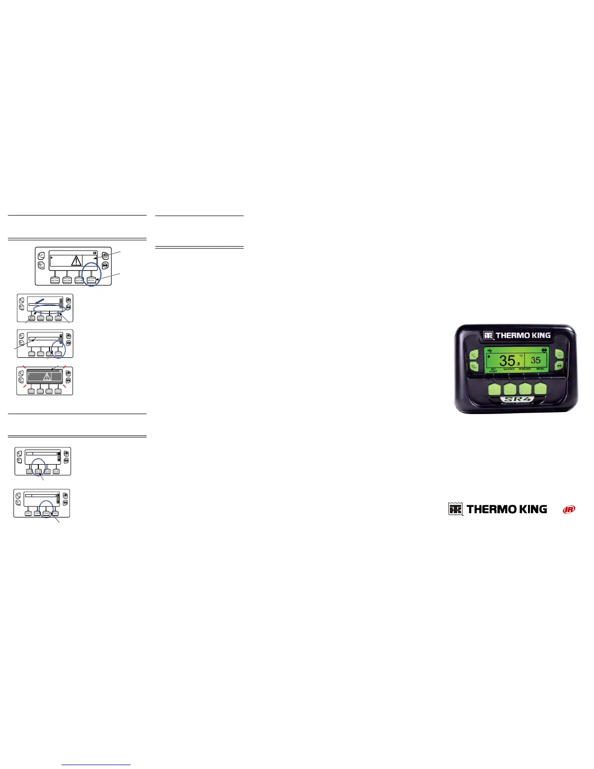
SR-4
Smart Reefer™ 4
Microprocessor
Driver Guide to
Simple
Operation
TK 55771-2-PC (Rev. 0, 01/14) ©Thermo King Corporation
522 Battery Temperature Sensor Alarm
523 Battery Temperature Sensor Alarm
524 Generator Operational Limit V out to
Frequency Ratio
525 Generator Frequency Range Fault
526 Generator Operational Limit Output Current
527 Reserved
528 Controller Not Receiving Messages From
Battery Charger
529 Check Fuel Pump Circuit
530 Low Pressure Differential
531 Check Economizer Pressure Sensor
538 Engine J1939 CAN Datalink Degraded
539 Engine J1939 CAN Datalink Failed
599 Engine Service Tool Connected
600 Check Crankshaft Speed Sensor
601 Check Camshaft Speed Sensor
602 Check Intake Throttle Position Sensor
603 Check Exhaust Pressure Sensor
604 Check Coolant Temperature Sensor
605 Check Fresh Air Temperature Sensor
606 Reserved
607 Check Fuel Temperature Sensor
608 Check Rail Pressure Sensor
609 Check Intake Pressure Sensor
610 Check Atmospheric Pressure Sensor
611 Check Glow Plug Circuit
612 Check Intake Throttle Circuit
613 Check Injector(s)
614 Check High Pressure Fuel Pump
615 Rail Pressure Fault
616 Engine Overspeed
617 Internal ECU Fault
618 Check EGR System
619 ECU Main Relay Fault
620 Reserved
621 Reserved
622 Reserved
623 TRU CAN Message Timeout
624 Check Intake Air Temperature Sensor
625 Check Intake Air Temperature Sensor
626 Check Exhaust Temperature Sensor
699 Unknown ECU Fault
 Loading...