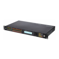
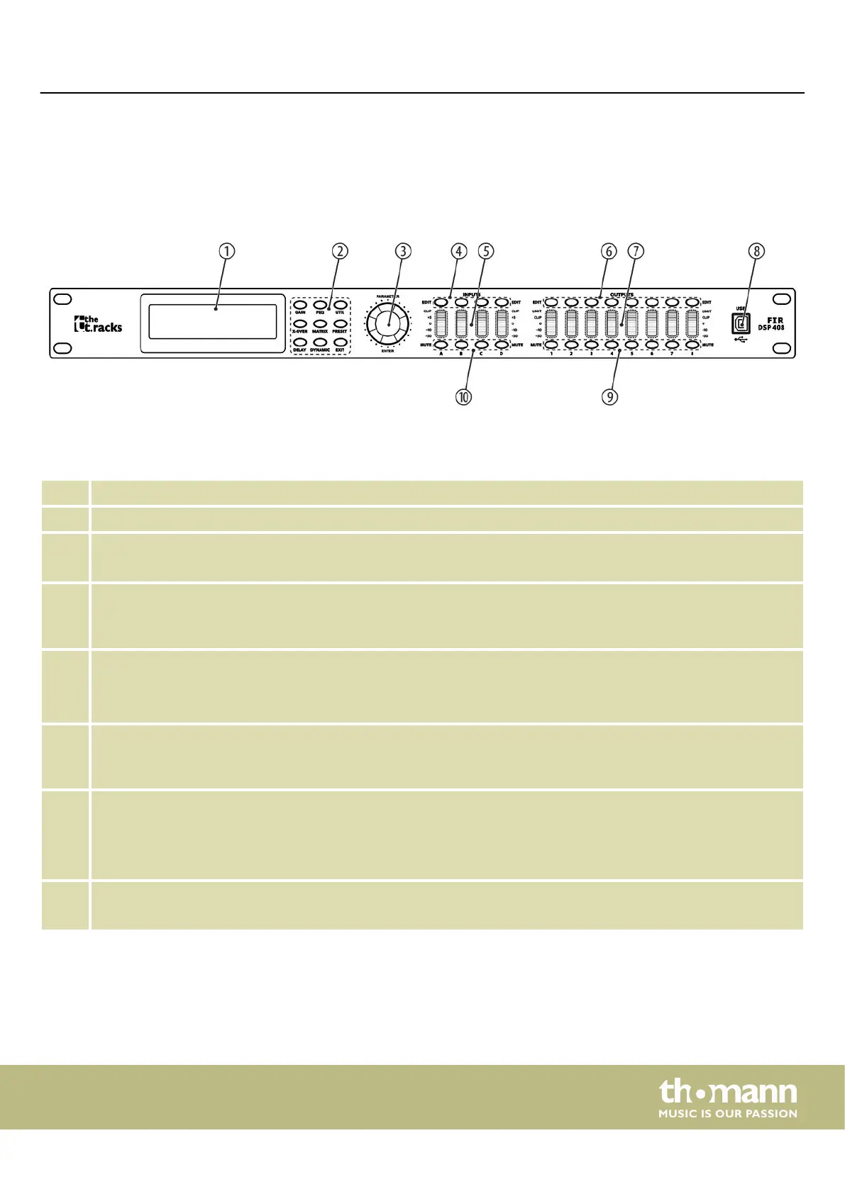
5 Connections and controls
1 Display
2 Buttons for direct selection of a parameter. Use [EXIT] to exit the Edit mode.
3 [ENTER / PARAMETER]
Rotary switch
4 [EDIT]
Buttons for selecting the Edit mode for the respective input channel. The set parameters of the selected channel
appear in the display.
5 [INPUTS]
Level meter for the input channels.
The red [CLIP] LEDs indicate overloading (clipping). In this case, the level of the input signal is too high.
6 [EDIT]
Buttons for selecting the Edit mode for the respective output channel. The set parameters of the selected channel
appear in the display.
7 [OUTPUTS]
Level meter for the output channels.
The red [CLIP] LEDs indicate overloading (clipping). In this case, the level of the output signal is too high. The red [LIMIT]
LEDs indicate that the built-in limiter has responded.
8 [USB]
USB port
Front panel
Connections and controls
FIR DSP 408
11
 Loading...