33
33
3
RMT3\08
09-2000
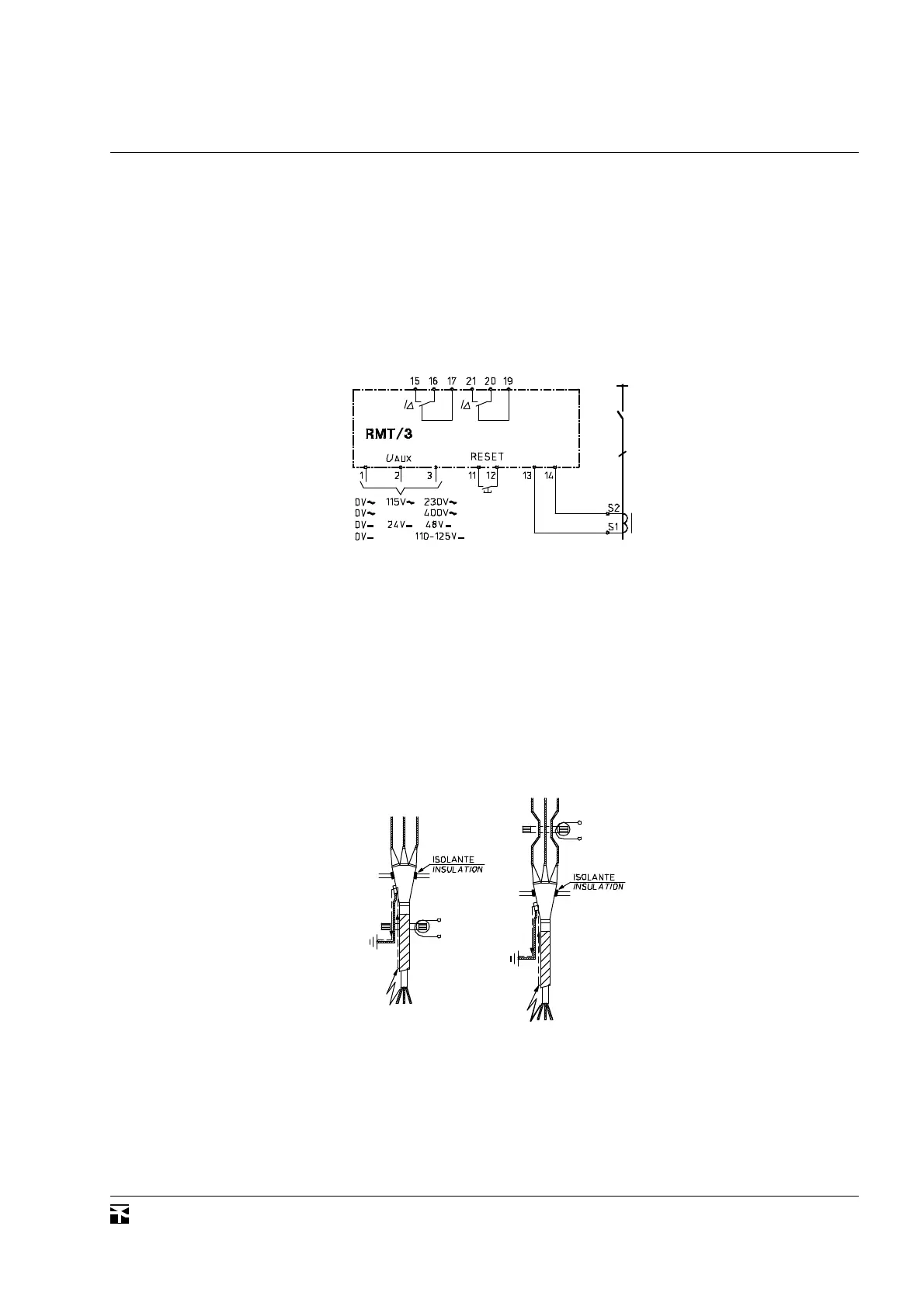
RMT/3
TRASFORMATORE TOROIDALE SOMMATORE
Il trasformatore toroidale deve essere collegato come specificato a
lato relativamente al circuito amperometrico. Deve essere attraver-
sato nel medesimo senso da tutti i
conduttori attivi della linea, compreso
il neutro (qualora sia distribuito). Que-
st'ultimo non deve essere collegato a
terra a valle del toroide. Il cavo o i
singoli conduttori, devono essere po-
sizionati in modo simmetrico rispetto
all'asse centrale del trasformatore
toroidale.
Nel caso in cui la linea protetta
abbia un'armatura metallica, questa
deve essere collegata a terra a valle del
toroide; pertanto se il toroide è instal-
lato a valle del manicotto terminale del
cavo armato, il relativo collegamento a
terra deve attraversare il toroide (altri-
menti nella condizione di guasto d'iso-
lamento del cavo verso l'armatura esterna, la corrente di terra
annullerebbe la corrente differenziale ed il relè amperometrico non
potrebbe operare); inoltre il manicotto terminale deve essere isolato
dal telaio di supporto, in modo che la corrente di terra circoli
solamente nel collegamento di terra che attraversa il toroide.
Se il toroide è posto a monte del manicotto terminale del cavo
armato, per cui esso è attraversato unicamente dai conduttori attivi,
il collegamento di protezione a terra del manicotto non deve attra-
versare il trasformatore toroidale.
Effettuando un collegamento permanente ai morsetti 11-12,
oppure posizionando su Aut. il microinterruttore frontale contras-
segnato RESET, si ottiene il ripristino automatico, a condizione che
la corrente residua rilevata sia scesa sotto il 90% della soglia
d'intervento.
By making a solid connection between terminals 11-12, or by
setting to Aut. the front plate microswitch referred to as RESET, the
function of automatic reset is performed, upon condition that the
residual current detected by the device drops below 90% of the
operation threshold.
CIRCUITO UTILIZZATORE DI SCATTO
Il circuito utilizzatore di scatto è costituito da due contatti di
scambio disponibili ai morsetti 15-16-17 e 19-20-21. In condizioni
normali, cioè con una corrente di terra inferiore alla soglia d'interven-
to, i contatti finali di scambio sono chiusi tra i terminali 16-17 e 19-
20. All'intervento del dispositivo i
contatti finali si chiudono tra i ter-
minali 15-16 e 20-21 e il LED rosso
di segnalazione si accende. Lo stato
del relè può essere predisposto
come normalmente diseccitato N.D.
o normalmente eccitato N.E. me-
diante il relativo microinterruttore
frontale; il dispositivo RMT/3 può
quindi funzionare a sicurezza posi-
tiva, nella quale il relè finale è man-
tenuto eccitato in condizione nor-
male e si diseccita in caso d'inter-
vento. Pertanto in condizioni nor-
mali i contatti finali sono chiusi tra i morsetti 15-16 e 20-21, mentre
all'intervento o al mancare della tensione ausiliaria o in caso di guasto
del dispositivo si chiudono tra i morsetti 16-17 e 19-20. Questo modo
di funzionamento è particolarmente indicato in associazione con
interruttori aventi il comando di apertura del tipo a mancanza di
tensione. In tal caso è opportuno che la tensione ausiliaria sia in c.c.,
per evitare aperture indesiderate dell'interruttore conseguenti ad
eventuali interruzioni della tensione di rete.
TRIP USER CIRCUIT
The trip user circuit comprises two change-over contacts con-
nected to terminals 15-16-17 and 19-20-21. In normal conditions,
that is with a residual current lower than the operation threshold,
the final contacts is closed between terminals 16-17 and 19-20. Upon
operation of the relay, the final
contacts closes between terminals
15-16 and 20-21 and the red LED
indicator turns on. Final relay can
be select as normally de-energized
N.D. or normally energized N.E.
by means a relative microswitch;
device RMT/3 can be therefore
operate in a positive safety mode,
in wich the final relay is kept ener-
gized in normal condition and is
deenergized in case of operation.
Therefore the final contacts is
closed between terminals 15-16
and 20-21 in normal condition, and closes between terminals 16-17
and 19-20 in case of operation or loss of auxiliary voltage or failure
of the device. This operation mode is strongly suggested when a
circuit breaker is used which has an opening device of loss of voltage
type. In such a circumstance the auxiliary voltage should be a d.c.
type, to make the circuit breaker not to open upon a possible mains
voltage interruption.
RING TYPE SUMMATION TRANSFORMER
The ring type transformer must be connected on side indicated
for the current circuit. It must be crossed in the same way by all the
live conductors of the line, including
the neutral (whenever distributed).
This one must not be connected to
earth downstream the transformer.
The cable or the single conductors
must be placed in symmetrical fashion
with respect to the axis of the ring
transformer.
In case the protected line be an
armored cable, the armor must be
connected to earth downstream the
ring type transformer; therefore if
the transformer is installed
downstream the gland of the armored
cable, its earth connection must pass
through the transformer (otherwise
in the event of insulation failure of
the cable toward the outer armour, the earth current would cancel out
the residual current and the measuring relay could not operate);
moreover the gland must be insulated from its supporting frame, in
order to make the earth current to flow in the earth connection
crossing the transformer.
If the transformer is installed upstream the armoured cable gland,
it is passed through only by the live conductor, then the earthing
conductor of the gland should not pass through the transformer.
 Loading...


