THERMOCOUPLE JUNCTION ADAPTER INSTALLATION
Unscrew thermocouple from gas valve and screw in Thermocouple Junction Adapter.
Screw thermocouple into Thermocouple Junction Adapter. Connect Linear Limit cables to
spade connections on Thermocouple Junction Adapter, (See Diagram C). NOTE: On 750
Millivolt (power pile) heaters, wire Linear Limit spill switch in series with high limit (ECO) of
heater.
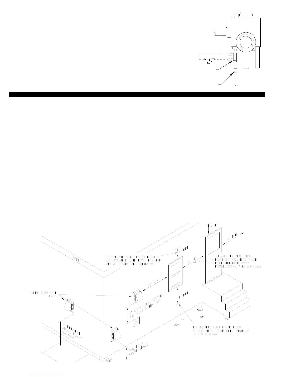
VENT HOOD TERMINATION CLEARANCES
CODE REQUIREMENTS
Failure to follow these installation instructions may violate applicable national and/or local codes. Terminate the vent system so that
proper minimum clearances are maintained as cited in the latest edition of the National Fuel Gas Code (NFPA # 54) and the latest edi-
tion of Chimneys, Fireplaces, Vents, and Solid Fuel Burning Appliances (NFPA #211), or as follows:
• Not be less than 7 feet above grade when located adjacent to public walk ways.
• At least 3 feet above any forced air inlet located within 10 feet.
• At least 4 feet below, 4 feet horizontally from or 1 foot above any door, window or gravity air inlet into any building.
• At least 12 inches above grade.
• So that the flue gases are not directed so as to jeopardize people, overheat combustible structures or enter buildings, and
• Not less than 2 feet from an adjacent building.
The vent terminal shall also not be installed closer than 3 feet from the inside corner of an L shaped structure.
1. Check vent pipe system for leakage. All vent system leaks must be sealed prior to installation of a power venter.
2. A vent system incorporating a Tjernlund VH1 Series vent hood should not exceed 575
o
F.
3. Termination of a sidewall vent system with a device other than the Tjernlund VH1 Series vent hood could affect system
performance and result in a possible safety hazard.
4. Plan the vent system layout to avoid the possibility of accidental contact with wiring or plumbing inside of walls.
5. Installation must be done by one experienced and familiar with venting of combustion appliances.
5
 Loading...