27
Maintenance
the engine.
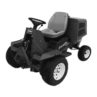
3. Move the cable until the speed control lever
contacts the idle speed screw.
Figure 36
1. Throttle cable
2. Cable clamp
3. Speed control lever
4. Idle speed screw
4. Tighten the cable clamp screw and check the engine
RPM setting.
ADJUSTING IDLE SPEED (Fig. 36)
1. Move the remote throttle control lever to the SLOW
position.
2. Loosen the lock nut on the idle speed screw.
3. Adjust the idle speed screw to obtain 1100 rpm.
4. Tighten the lock nut.
CHECKING THE PARKING BRAKE
1. Park the machine on a level surface, disengage the
PTO switch, set the parking brake and turn the
ignition key to “OFF” to stop the engine. Remove
the key.
2. The drive wheels must lock when the brake is
applied. Adjustment is required if the wheels turn
and do not lock; refer to Adjusting the Brake.
3. Release the brake; wheels should turn freely.
4. If both conditions are met, no adjustment is
required.
IMPORTANT: With the parking brake released, the
drive wheels must turn freely. If brake action and
free wheel rotation cannot be achieved, contact your
service dealer immediately.
ADJUSTING THE PARKING
BRAKE (Fig. 37)
If drive wheels do not turn when the brake lever is in the
OFF position, or the brake does not hold when the lever
is in the ON position, an adjustment is required.
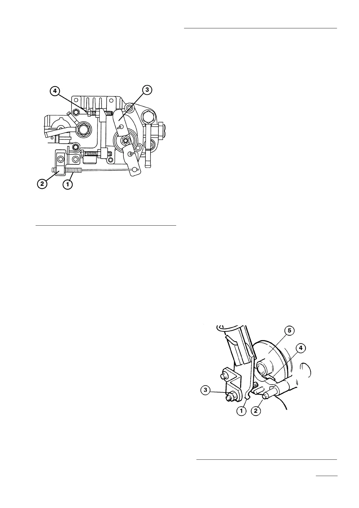
1. Move the brake lever to the ON position.
2. Measure the distance between the disc brake
actuating arm and the stop pin on the axle bracket
assembly. Distance should be less than 6 mm.
3. If the distance is greater than 6 mm, tighten the
locknut to decrease distance.
4. With the brake lever OFF, check the clearance
between the brake pads and the disc with a feeler
gauge. Correct clearance is approximately 2.5 mm
(.010 in.).
5. The actuating arm should be no more than 10 mm
away from STOP with the brake lever in the OFF
position.
Figure 37
1. Brake actuating arm
2. Stop pin
3. Locknut
4. Disc pad
5. Disc
 Loading...


