EasyManua.ls Logo

Toro 142-7070 - User Manual

Toro 142-7070
9 pages
Print Icon
To Next Page IconTo Next Page
Loading...
FormNo.4506-511RevB
FoamMarkerKit
KitNo.142-7070
InstallationInstructions
ForMid/MaxModelsSerialNo.413,950,474
Safety
SafetyAlertSymbol
ThisSafetyAlertSymbol(Figure1)isusedbothin
thisinstructionsheetandonthemachinetoidentify
importantsafetymessageswhichmustbefollowedto
avoidaccidents
Thissymbolmeans:ATTENTION!BECOMEALERT!
YOURSAFETYISINVOLVED!
g000502
Figure1
SafetyAlertSymbol
Thesafetyalertsymbolappearsaboveinformation
whichalertsyoutounsafeactionsorsituationsand
willbefollowedbythewordDANGER,WARNING,or
CAUTION.
DANGER:Indicatesanimminentlyhazardous
situationwhich,ifnotavoided,Willresultindeathor
seriousinjury.
WARNING:Indicatesapotentiallyhazardoussituation
which,ifnotavoided,Couldresultindeathorserious
injury.
CAUTION:Indicatesapotentiallyhazardoussituation
which,ifnotavoided,Mayresultinminorormoderate
injury.
Thismanualusestwootherwordstohighlight
information.Importantcallsattentiontospecial
mechanicalinformationandNoteemphasizesgeneral
informationworthyofspecialattention.
WARNING
Whilemaintenanceoradjustmentsarebeing
made,someonecouldstarttheengine.
Accidentalstartingoftheenginecould
seriouslyinjureyouorotherbystanders.
Removethekeyfromtheignitionswitch,
engageparkingbrake,andpullthewire(s)
offthesparkplug(s)beforeyoudoany
maintenance.Alsopushthewire(s)asideso
itdoesnotaccidentallycontactthespark
plug(s).
Note:Determinetheleftandrightsidesofthe
machinefromthenormaloperatingposition.
Note:Parkthemachineonalevelsurface.Make
sureallmovingpartshavestopped,parkingbrakeis
engaged,thekeyhasbeenremoved,andthespark
plugwirehasbeendisconnected.Allowthemachine
tocoolbeforestartingtheseinstructions.
GeneralSafety
Important:Beforestartingtheseinstructions:
—makesuretoweartheappropriatePersonal
ProtectiveEquipment(PPE)andfollowallsafety
precautionsasstatedintheOperatorsmanual.
—makesuretheentirespraysystemhasbeen
properlycleaned.
CAUTION
Chemicalsarehazardousandcancause
personalinjury.
Readthedirectionsonthechemicallabels
beforehandlingthechemicalsandfollow
allmanufacturerrecommendationsand
precautions.
Keepchemicalsawayfromyourskin.
Shouldcontactoccur,washtheaffected
areathoroughlywithsoapandcleanwater.
Weargoggles,gloves,andanyother
protectiveequipmentrecommendedbythe
chemicalmanufacturer.
OriginalInstructions(EN)
PrintedintheUSA
AllRightsReserved
*4506-511*
Question and Answer IconNeed help?

Do you have a question about the Toro 142-7070 and is the answer not in the manual?

Summary

Safety

Safety Alert Symbol

Explains the meaning and usage of the safety alert symbol for hazard identification.

Safety Terminology Definitions

Defines DANGER, WARNING, CAUTION, and NOTE terms for hazard communication.

Pre-Maintenance Safety Procedures

Outlines crucial steps to prevent accidental engine starting during maintenance.

General Safety

Personal Protective Equipment (PPE)

Stresses the importance of wearing appropriate PPE and following manual safety precautions.

Chemical Handling Safety

Provides guidelines for safe chemical handling, skin contact, and protective gear.

Safety and Instructional Decals

Decal Care and Application

Instructions on maintaining, replacing, and affixing safety and instructional decals.

Loose Parts

Installation Instructions

Mechanical Assembly and Hose Routing

Details attaching nozzles, mounting tank, and routing spray hoses.

Control Panel Switch Installation

Guides cutting the panel and installing the control switch.

Operating Instructions

Initial System Check

Verifies the foam marker is off when the key and switch are OFF.

Spray Activation and Control

Explains using the switch and foot button to operate the spray system.

Parts List

Overview

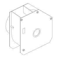
This document describes the Foam Marker Kit, Kit No. 142-7070, Form No. 4506-511 Rev B, for Mid/Max Models Serial No. 413,950,474. It provides installation instructions, general safety guidelines, and a parts list for the kit.

Function Description:

The Foam Marker Kit is designed to assist operators in maintaining consistent spray patterns by marking previously sprayed areas with foam. This helps prevent overspray or missed areas, improving efficiency and reducing chemical waste. The system includes a foam tank, pump, nozzles, and associated hoses and electrical components to generate and dispense foam markers. The foam marker system is controlled by a rocker switch, allowing the operator to turn the foam spray on or off as needed. A foot button is also integrated for momentary activation of the spray pump.

Important Technical Specifications:

  • Foam Tank Capacity: The kit includes a 2-gallon foam marker tank (Part No. 142-7063 or 146-1100).
  • Nozzles: Two foam marker nozzles (Part No. 135-6661) are included for left and right side application.
  • Hose: A 144-inch length of 0.50 ID spray hose (Part No. 135-6665) is provided for routing the foam.
  • Electrical Components: The system utilizes a rocker switch (Part No. 100-8590), a mini relay (Part No. 99-7430), and a foam marker harness (Part No. 142-7426) and accessory relay harness (Part No. 142-7731) for electrical integration.
  • Pump: A motor-diaphragm compressor (Part No. 146-1710) and a foam marker pump (Part No. 146-1711) are central to the foam generation. A liquid pump (Part No. 142-0097) is also listed.
  • Fasteners: Various screws (e.g., 135-6272, 135-6221, 135-6280) and nuts (e.g., 135-6109, 135-6108) are specified for mounting components.
  • Tie-Cables: Multiple tie-cables (Part No. 3290-378 and 1-303287) are used for securing hoses and harnesses.
  • Fittings: Includes a barb tee fitting (Part No. 138-2751), a 90-degree elbow fitting (Part No. 135-8196), and a straight fitting (Part No. 142-0105).

Usage Features:

  • Safety Alert System: The manual emphasizes safety with a Safety Alert Symbol (!), indicating DANGER, WARNING, or CAUTION messages. Operators are warned about potential hazards like accidental engine starting and chemical exposure.
  • Control Panel Integration: The foam marker system integrates into the existing control panel of the machine. A dedicated rocker switch (Part No. 100-8590) is installed to the right of the spray switch.
  • On/Off Operation: The system can be turned on or off using the rocker switch. The decal (Part No. 142-8574) provides clear visual cues for "On" and "Off" positions.
  • Momentary Spray Activation: A foot button allows for momentary activation of the spray pump, providing flexible control during operation.
  • Dual Nozzle System: The kit includes two foam marker nozzles, one for the left and one for the right side of the spray boom, ensuring comprehensive marking.
  • Hose Routing: Detailed instructions are provided for routing the spray hose from the foam marker tank, under the frame, and along the boom to the nozzles, ensuring proper installation and preventing interference.
  • Electrical Connection: The foam marker harness connects to an accessory relay harness, which then plugs into the machine's main harness under the control panel, simplifying electrical integration.

Maintenance Features:

  • Safety Decals: The manual stresses the importance of keeping all safety signs legible and replacing worn, damaged, or missing decals (Part No. 142-8574). New decals can be obtained from authorized dealers.
  • Cleaning: Before starting installation, the entire spray system must be properly cleaned.
  • Chemical Handling: Operators are instructed to read chemical labels, follow manufacturer recommendations, and wear appropriate Personal Protective Equipment (PPE) such as goggles and gloves when handling chemicals. Skin contact should be avoided, and affected areas should be washed thoroughly with soap and clean water if contact occurs.
  • Pre-Installation Checks: Before installation, the engine must be stopped, parking brake engaged, key removed, and spark plug wires disconnected to prevent accidental starting. The machine should be allowed to cool.
  • Post-Installation Checks: After installation, the ignition key should be turned to ON, and the spray system and check for leaks should be operated before returning the sprayer to service.
  • Harness Routing: Instructions emphasize routing the foam marker harness underneath the control panel and securing it with tie-cables to prevent damage and ensure a tidy installation.
  • Component Replacement: When replacement components are installed, ensuring that current safety signs are affixed to the replaced components is crucial.
  • Troubleshooting: The operating instructions provide guidance on how to turn on the foam marker, noting that the tank should be off when the switch is depressed down on the "O" side. If the foam marker operates opposite of this, the switch needs to be removed and rotated 180 degrees.

Toro 142-7070 Specifications

General IconGeneral
BrandToro
Model142-7070
CategoryLawn Mower Accessories
LanguageEnglish

Related product manuals