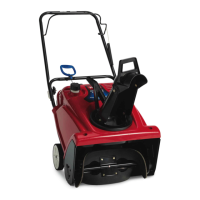
AdjustingtheControlCable
1.Slideupthespringcoverandunhookthespringfrom
theadjusterlink(Figure26).
Figure26
1.Adjusterlink
3.Springcover
2.Z-tting
4.Unhookthespringhere.
Note:Youcanpulluptheadjusterlinkandcableto
makeunhookingthespringeasier.
2.MovetheZ-ttingtoahigherorlowerholeonthe
adjusterlinkasneededtoobtainthe1/16inchto1/8
inch(2mmto3mm)gapbetweenthecontrolbarand
thehandle(Figure25).
Note:MovingtheZ-ttinghigherdecreasesthegap
betweenthecontrolbarandthehandle;movingit
lowerincreasesthegap.
3.Hookthespringtotheadjusterlinkandslidethespring
coverovertheadjusterlink.
4.Checktheadjustment;refertoCheckingtheControl
Cable(page12).
Note:Afterextendeduse,thedrivebeltmaywear
andloseitsproperbelttension.Ifthedrivebeltslips
(continuouslysqueals)underaheavyload,disconnect
thespringfromtheadjustorlinkandmovetheupper
endofthespringtotheholethatisfurtherfrom
thepivotpointinthecontrolbar(Figure27).Then
connectthespringtotheadjustorlinkandadjustthe
controlcable.
Figure27
1.Removetheupperendof
springfromthishole.
3.Pivotpoint
2.Inserttheupperendof
springintothishole.
4.Upperendofspring
Note:Thebeltmayslip(squeal)inwetconditions;
todryoutthedrivesystem,starttherotorandrunit
withoutaloadfor30seconds.
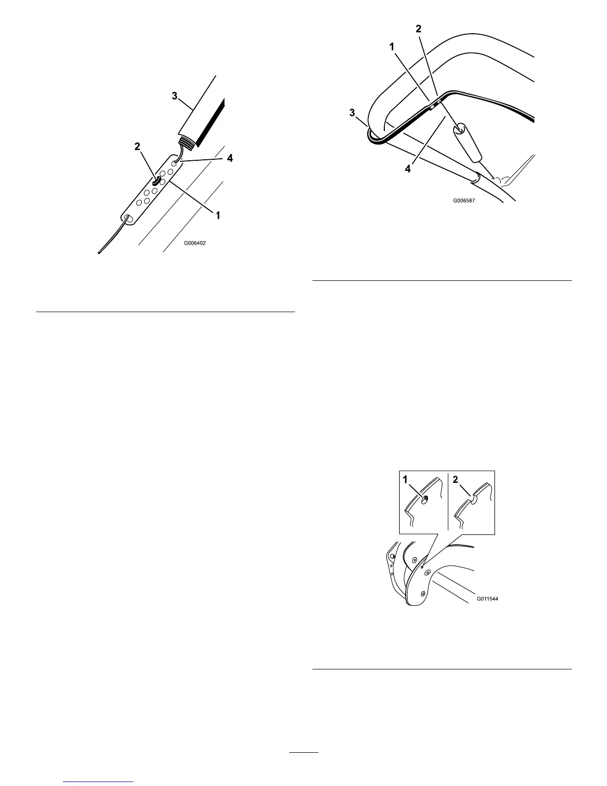
InspectingtheRotorBlades
ServiceInterval:Yearly—Inspecttherotorbladesandhave
anAuthorizedServiceDealerreplacethe
rotorbladesandscraperifnecessary.
Beforeeachsession,inspecttherotorbladesforwear.When
arotorbladeedgehasworndowntothewear-indicatorhole,
haveanAuthorizedServiceDealerreplacetherotorblades
andthescraper(Figure28).
Figure28
1.Thewear-indicatorholeis
intact;youdonotneedto
replacetherotorblades.
2.Thewear-indicatorholeis
exposed;replacetherotor
blades.
13
 Loading...