•debris
•properalignmentandseatingofthepinsinsidetheconnectors
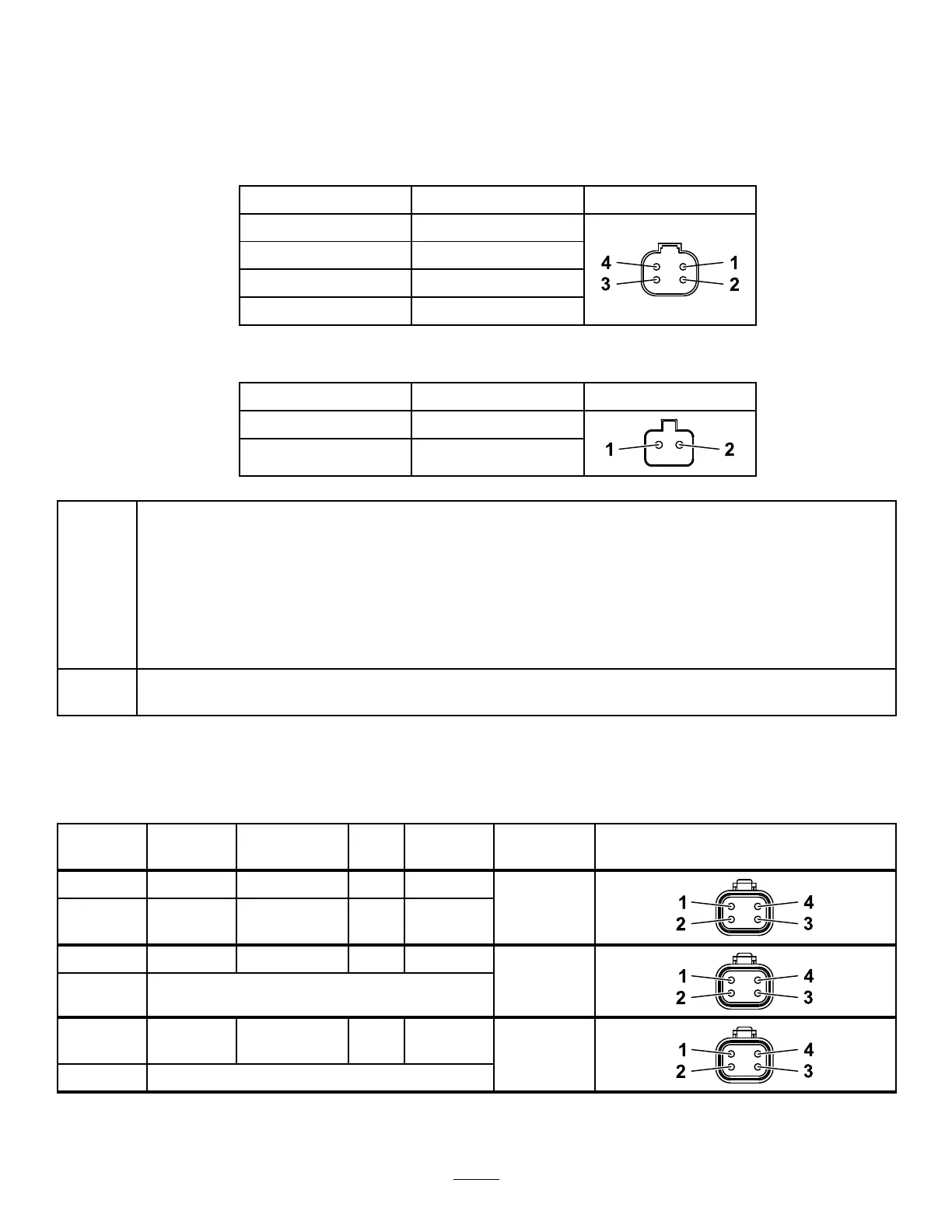
5.Inspectthe2cuttingreelmotorcableconnectorsforproperwirecolorperpin,asshowninthefollowing2
tables.
CuttingReelMotor,4-PinConnector
PinNumber
WireColor
1White(W)
2Blue(BU)
3Yellow(Y)
4Green(GN)
CuttingReelMotor,2-PinConnector
PinNumber
WireColor
1
Red(R)
2
Black(BK)
PassThewiringinspectioncheckpassed.
•Leavethe2cuttingreelmotorcableconnectorsunpluggedfromthee-reelsharnessconnectors
P17andP18.
•Leavethe48Vpowerdisconnectedfromthecuttingunitsfromthesystem.Thisprevents
unexpectedoperationofcuttingunits.RefertoConnectingandDisconnectingthe48VPower
totheCuttingReelMotors(page18).
•GotoStep4.
Fail
Oneormoreoftheinspectionchecksfailed.Repairorreplacethewornordamagedparts.Goto
ReturningtheMachinetoService(page21)andfollowthestepslisted.
Step3:TesttheCANbuswiringine-reelsharnessconnectorP17.
Useamultimetertotesttheresistancebetweenthefollowingpairsoflocations:
LocationHarness
Connector
Pin
Wire
Color
Expected
Reading
ConnectorGraphic
1E-reelsP173
Yellow(Y)
2E-reelsP174
Green
(GN)
54to66
ohms
1E-reelsP173
Yellow(Y)
2
Chassisground
Open
(innite)
1E-reelsP174
Green
(GN)
2
Chassisground
Open
(innite)
67

 Loading...