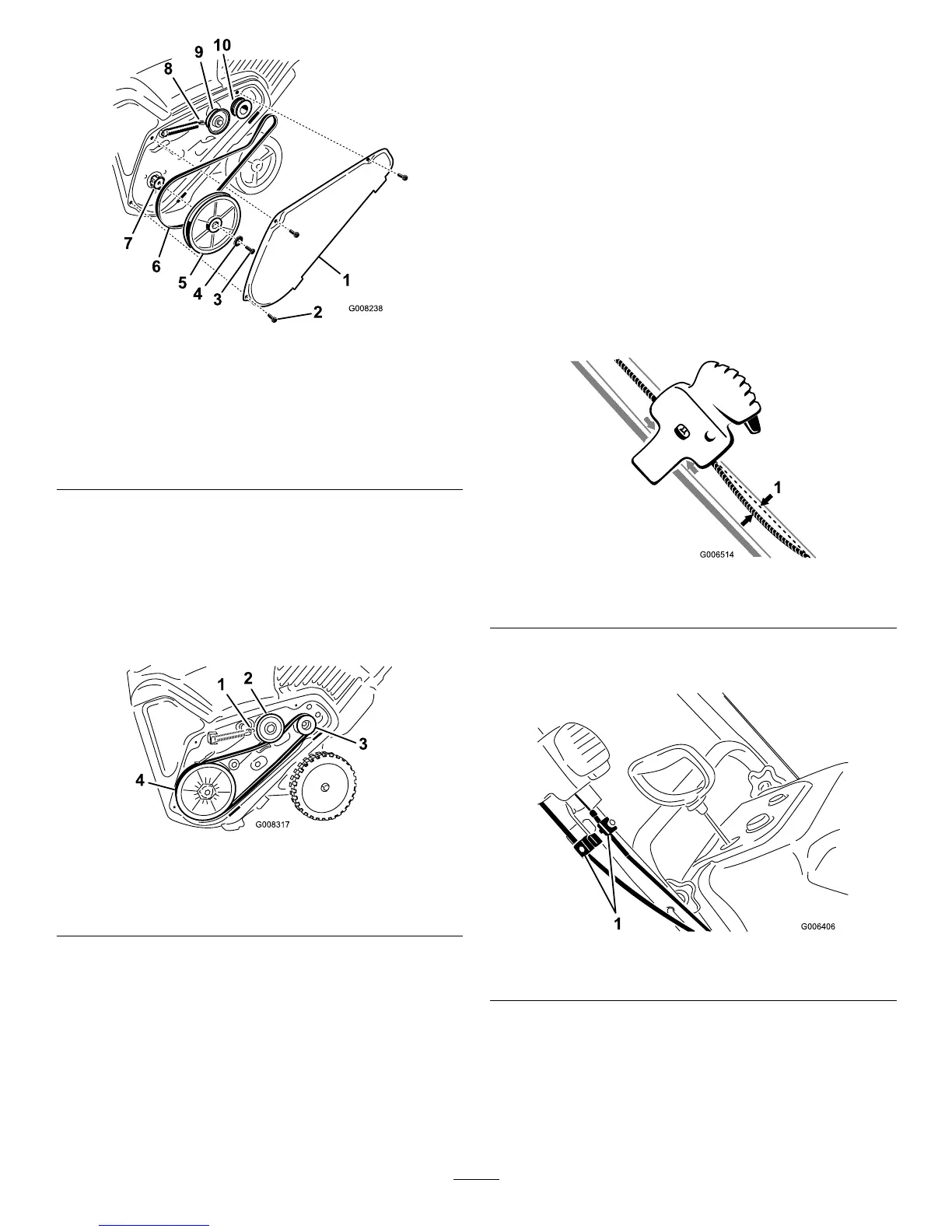
Figure38
1.Drivebeltcover6.Drivebelt
2.Bolt(3)7.Rotorshaft
3.Rotorpulleybolt
8.Brakespring(unhookfrom
idlerarmhere)
4.Curvedwasher
9.Idlerpulley
5.Rotorpulley10.Enginepulley
2.Unhookthebrakespringfromtheidlerarmtorelease
thebelttension(Figure38).
3.Removethescrewandcurvedwasherthatholdsthe
rotorpulley(
Figure38).
4.Removetherotorpulleyandthedrivebelt(
Figure38).
5.Installthenewdrivebelt,routingitasshownin(Figure
39
).
Figure39
1.Brakespring(installon
idlerarmhere)
3.Enginepulley
2.Idlerpulley4.Rotorpulley
Note:Routethenewdrivebeltrstaroundtheengine
pulley,thentheidlerpulley,andnallyaroundthe
looserotorpulleypositionedjustabovetherotorshaft
(Figure38).
6.Installtherotorpulleyontotherotorshaft(
Figure38).
7.Installthecurvedwasherandtherotorpulleyboltand
tightenthemsecurely(Figure38).
Note:Theconcavesideofthecurvedwashergoes
againsttheoutsideofthepulley.
8.Installthebrakespringontotheidlerarm(Figure39).
9.Installthedrivebeltcoverwiththeboltsyouremoved
instep1.
Note:Ensurethatthedrivebeltisproperlyadjusted
andoperating;refertoCheckingtheControlCableand
AdjustingtheControlCable.
AdjustingtheQuickShoot™
Control
Ifthereismorethan1/2inch(13mm)ofslackintheQuick
Shootcable(Figure40)orthedischargechutedoesnotrotate
leftandrightinequalangles,adjusttheQuickShootcontrol
cables.
Figure40
1.1/2inch(13mm)maximumslack
1.LoosenthetwoQuickShootcontrolcableclamps
(Figure41).
Figure41
1.Cableclamps
2.PositiontheQuickShootcontrolbetweenthetwo
arrowslocatedontherighthandsideoftheupper
handle(Figure42).
18
 Loading...